杭州编码器
Hangzhou Technology Co., Ltd.
Email:19957825969@163.com Tel: 0571-86985191 19957825969 (Wechat) QQ:1927418516
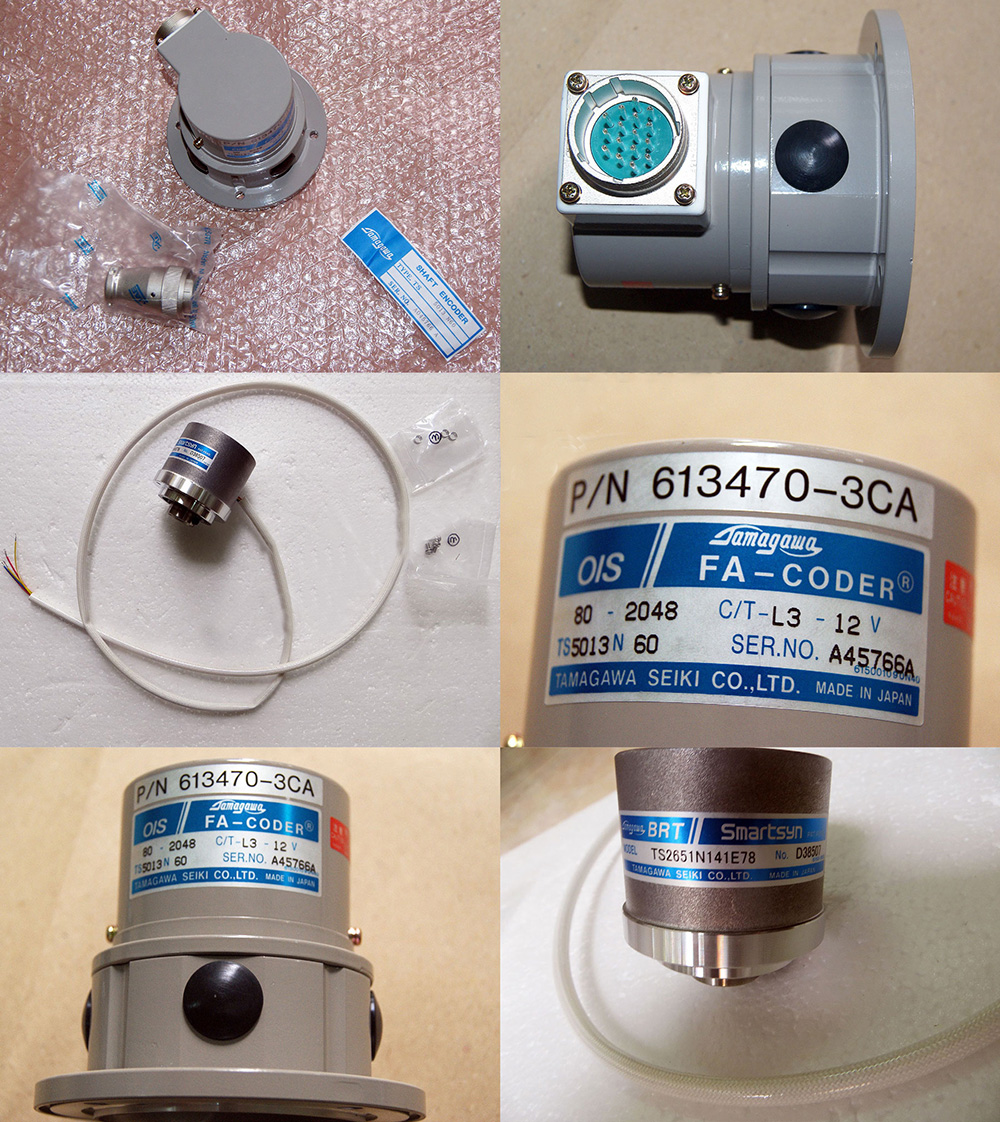
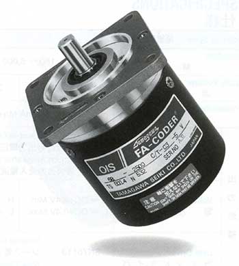
Tamagawa多摩川编码器

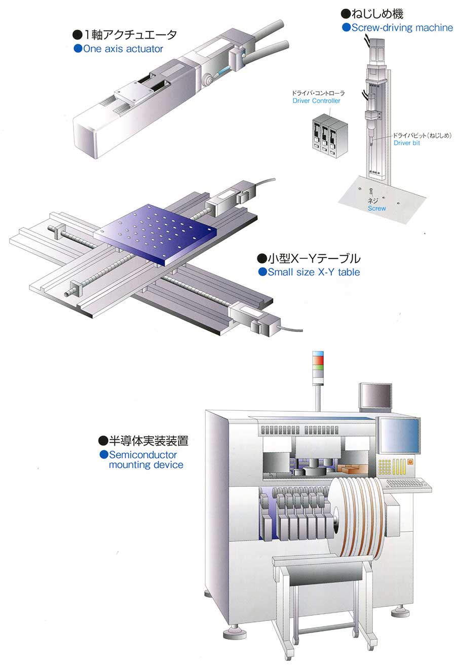
| Applications | Intrumentation | Industrial | Milling | ||
| Features | Ultra small size | Small size and low cost | Wide range of resolution, a lot of options | Ultra rugged Model | |
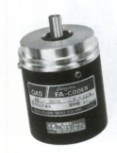
| Series | OIS28 |
OIS38 |
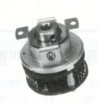
OIS66 |
OIS68 |
OIS128 |
| Model No. | TS51 |
TS53 |
TS51 |
TS50 |
TS50 |
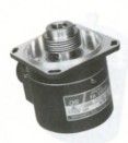
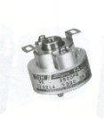
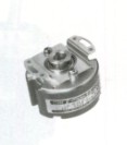
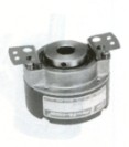
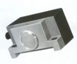
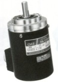
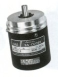
| External Appearance | 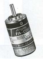 |
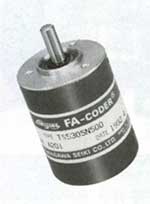 |
 |
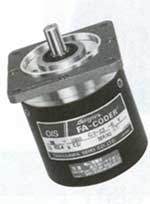 |
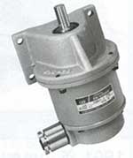 |
| Page | 9, 10 | 11, 12 | 13, 14 | 15, 16 | 17, 18 |
| Resolution (Counts/Turn) | 100~2000C/T | 100~2500C/T | 100~5000C/T | 25~5000C/T | |
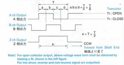
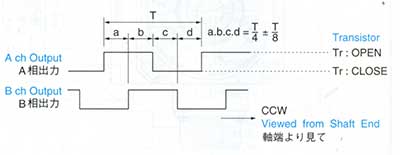
| Output Phase | A, B Phase | A, B, Z Phase | A, B Phase | ||
| Max Response Frequency | 80kHz | 125, 200kHz | 125kHz | 25kHz | |
| Supply Voltage | DC+5V | DC+5V~+12V | DC+5, +12V | DC+24V | |
| Consumption Current (NOTE1) | 100mA Max | 20mA Max | 300mA Max | ||
| Output Form | Open Collector | Open Collector Line Driver |
Voltage, Open Collector, Line Driver | Voltage Complementaly |
|
| NOTE2 Shaft Loading Radial |
21.6N (2.2kgf) |
98N (10kgf) |
392N (40kgf) |
||
| NOTE2 Shaft Loading Axial |
12.7N (1.3kgf) |
10.8N (1.1kgf) |
12.7N (1.3kgf) |
49N (5kgf) |
|
| Starting Torque | 2.9x10⁻³ N.m (30gf.cm Max) |
4.4x10⁻³ N.m (45gf.cm Max) |
2.9x10⁻³ N.m (30gf.cm Max) |
9.8x10⁻² N.m (1kgf.cm Max) |
0.2N.m (2kgf.cm Max) |
| Protection (NOTE3) | IP=50 | IP=52 | IP=57 | ||
| Operating Temp.Range | 0~+60°C | -10~+70°C | 0~+50°C | ||
| Vibration (NOTE4) | 49m/s2 (5G) |
98m/s2 (10G) |
|||
| Shock (NOTE5) | 490m/s2 (50G) |
980m/s2 (100G) |
|||
| Mass | 0.2kg Max | 0.15kg Max | 0.5kg Max | 1kg Max | 7kg Max |
| Super Precision Machine Tools | Motor Controls | Machine Tools | |||
| High resolution, high reliability and low cost | Hollow Shaft Small Size |
Hollow Shaft Small Size |
Hollow Shaft Medium Shaft |
Magnetic Encoder | |
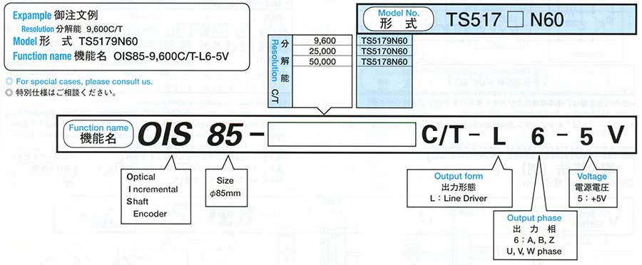
OIS85 |
OIS90 |
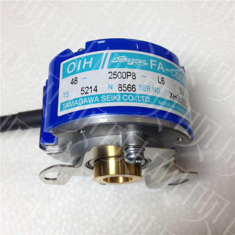
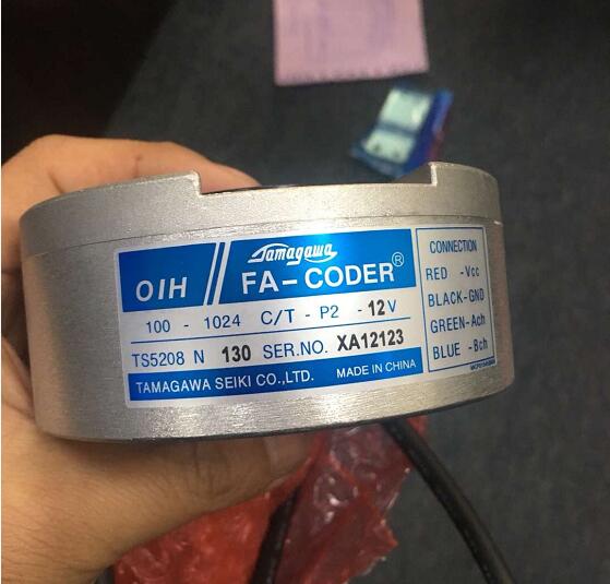
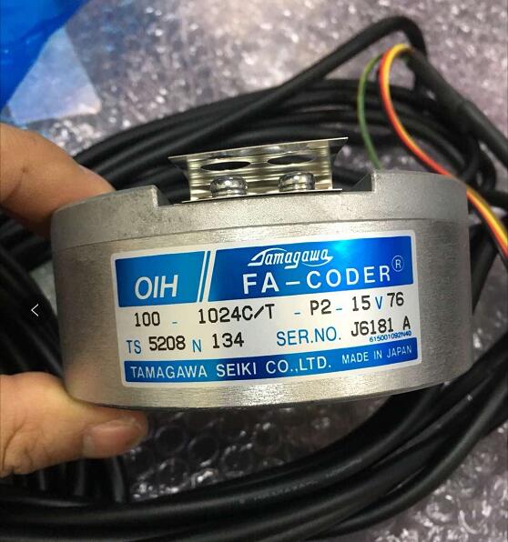
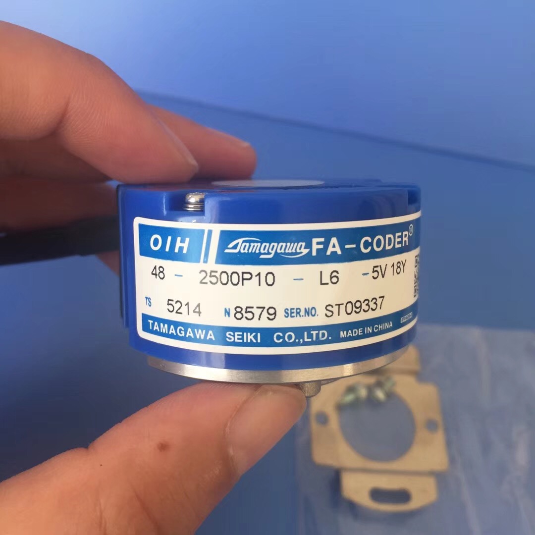
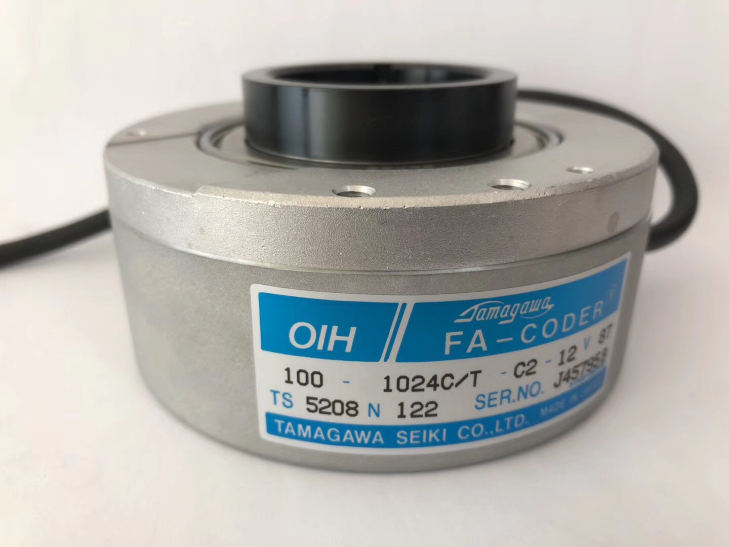
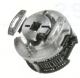
OIH35 |
OIH48 |
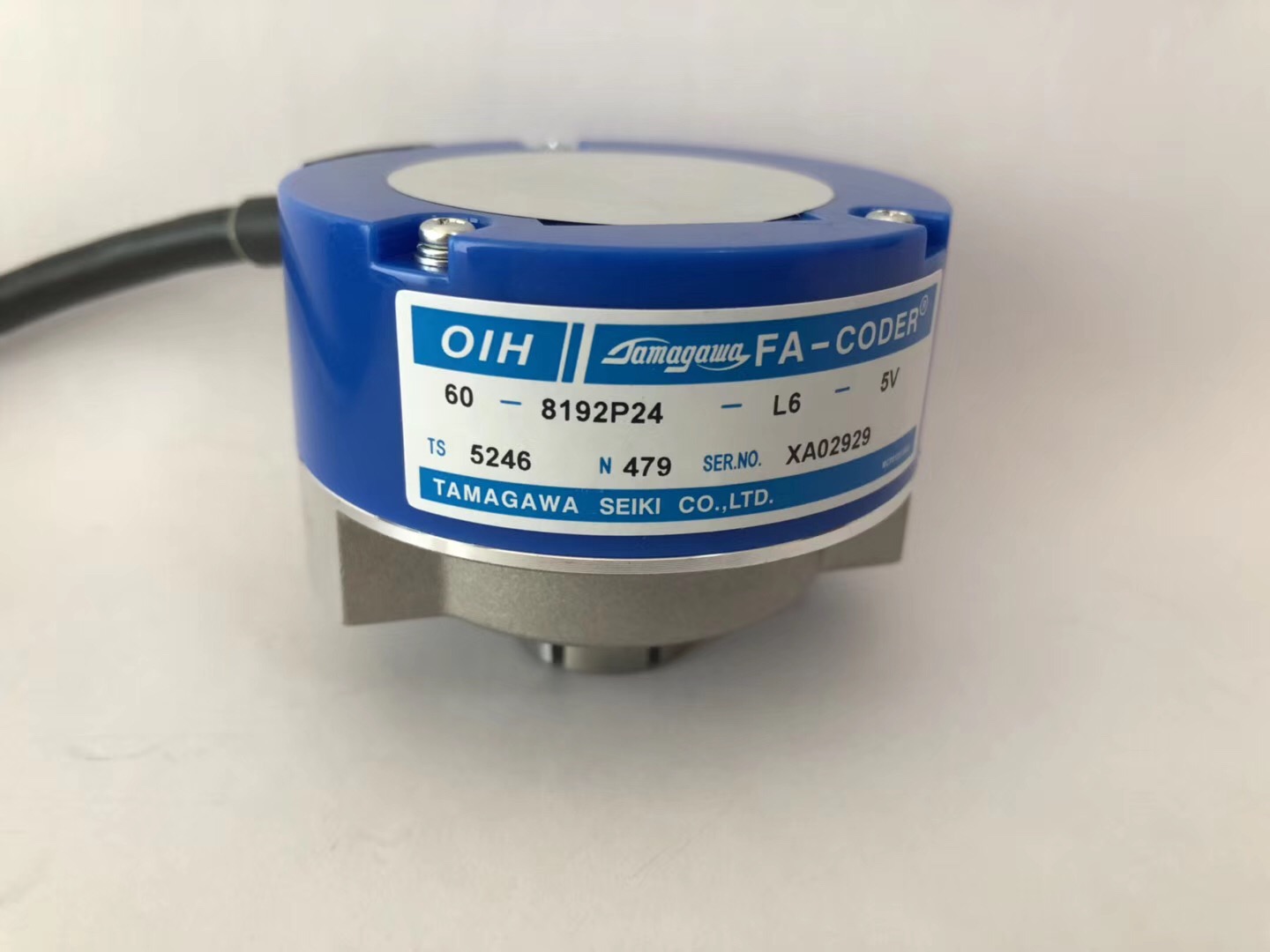
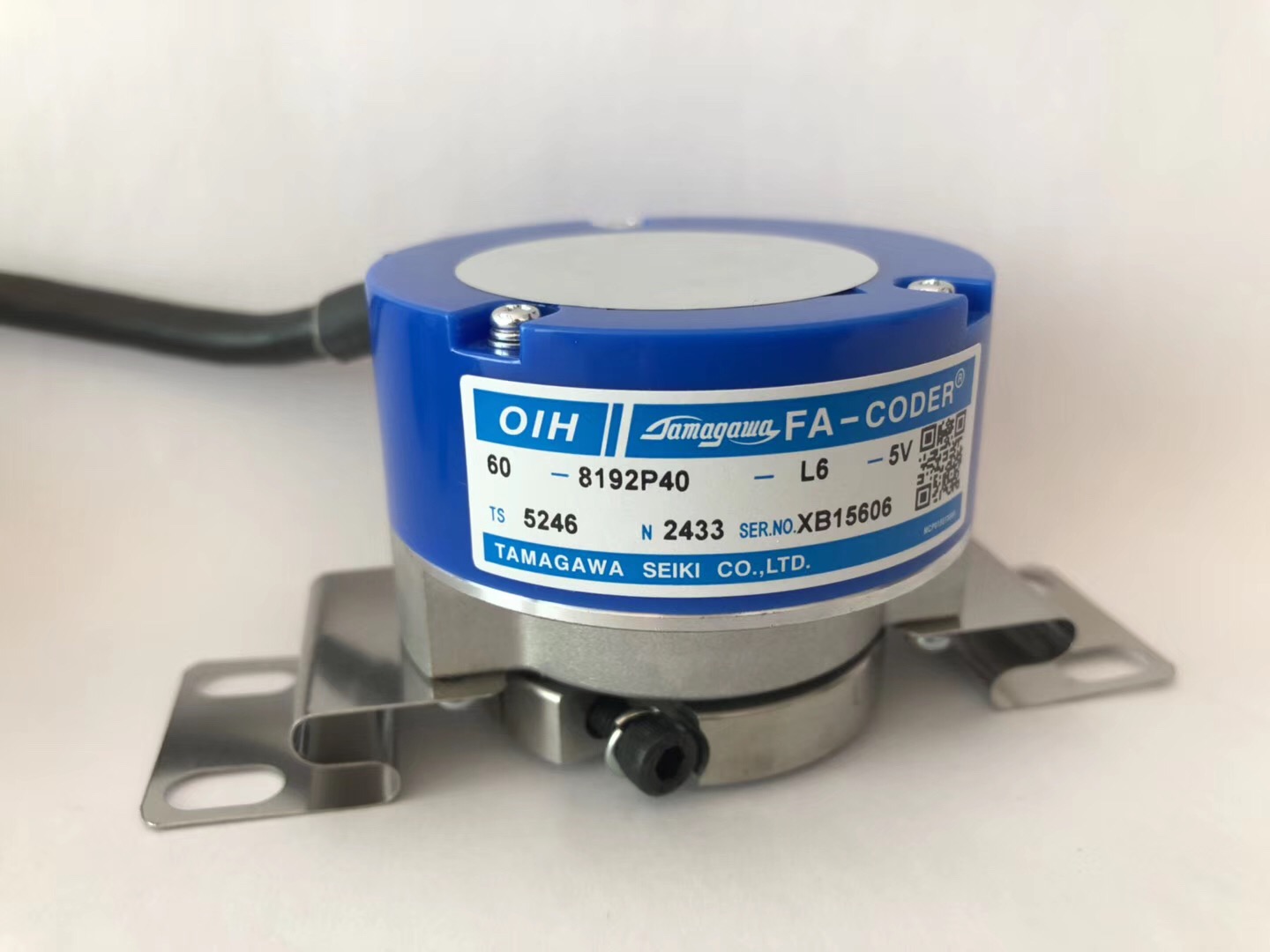
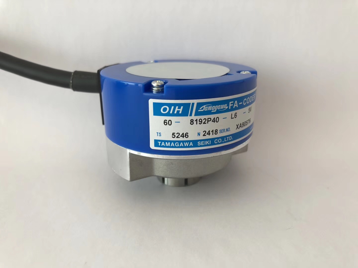
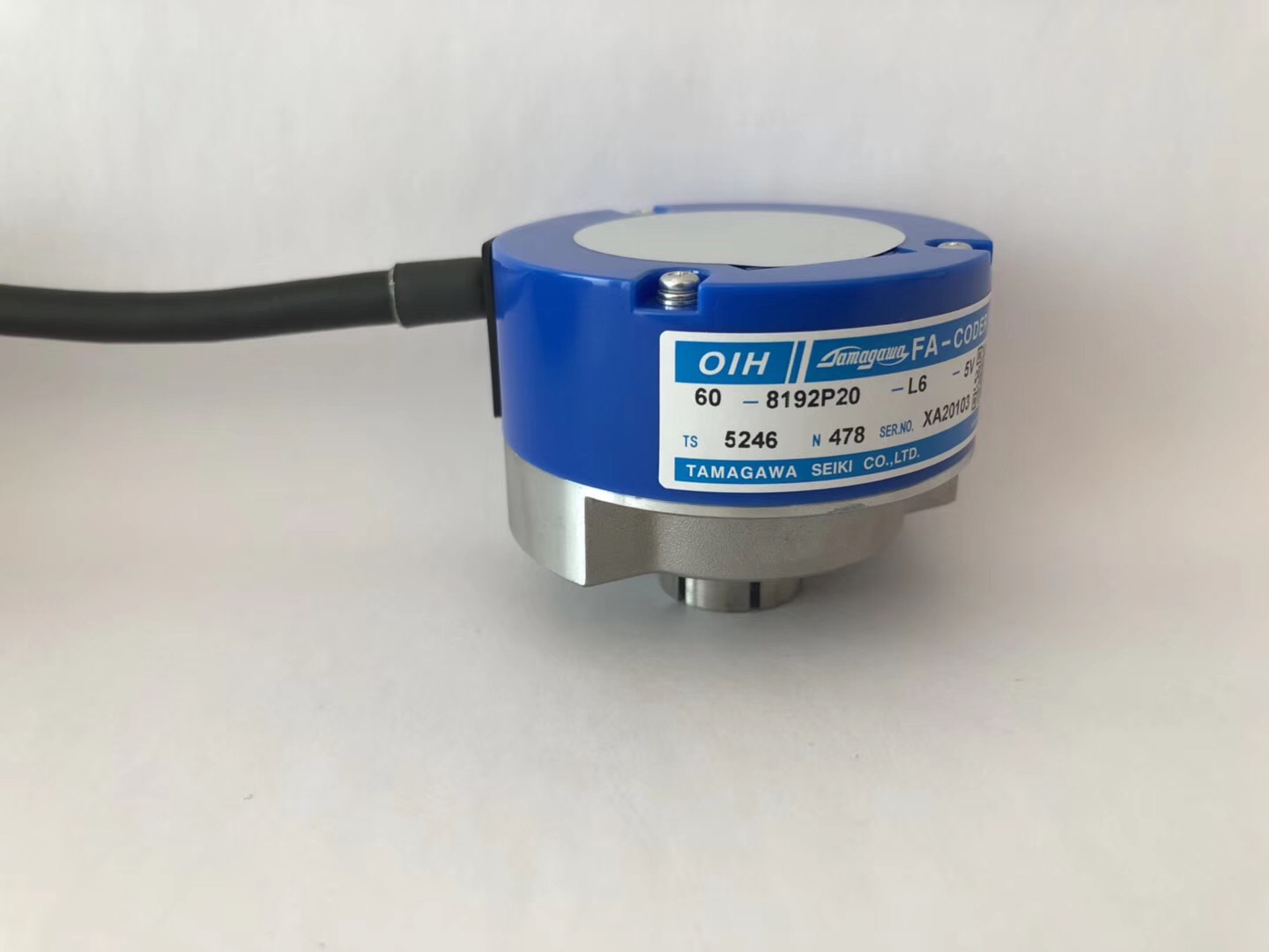
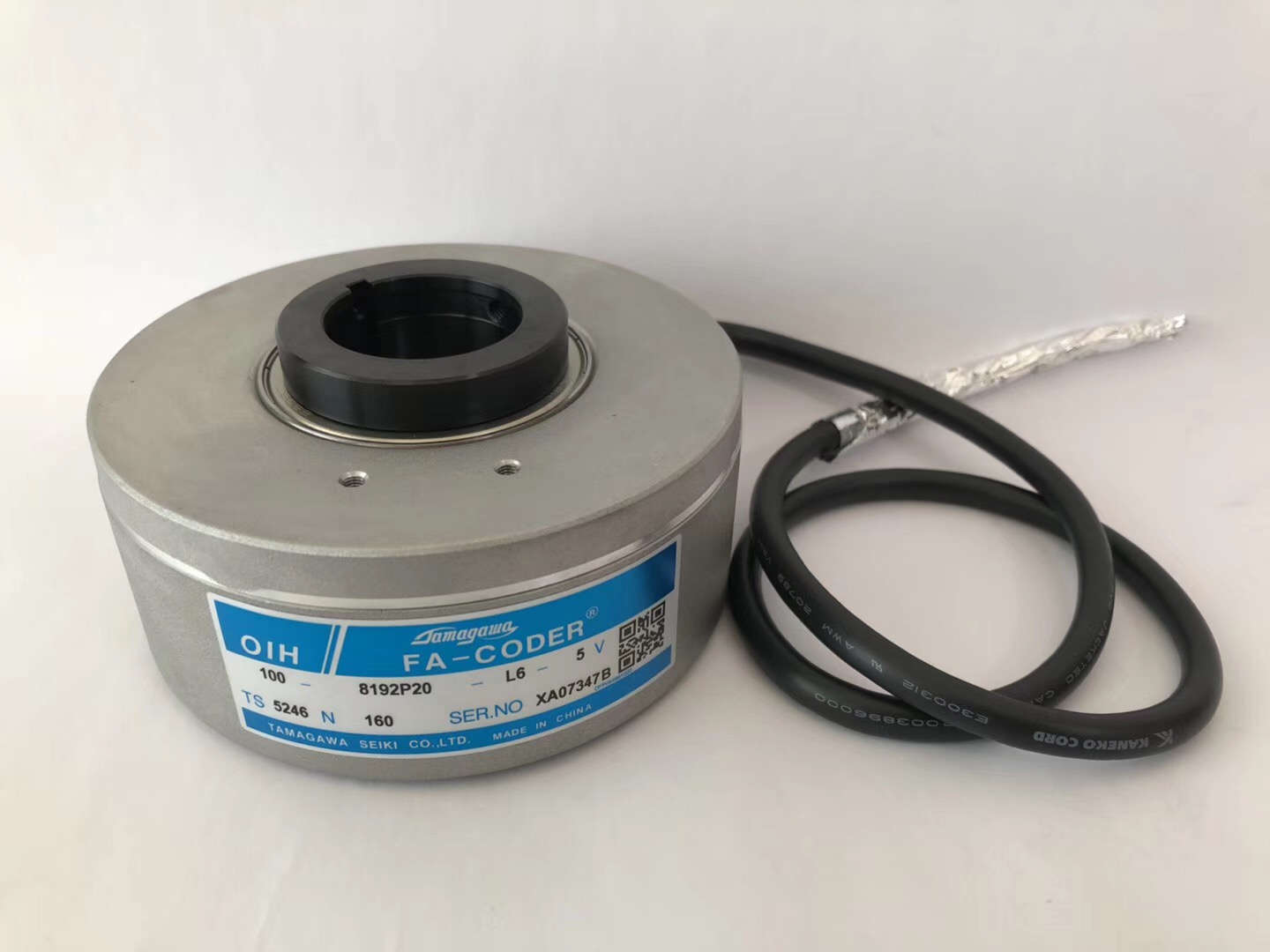
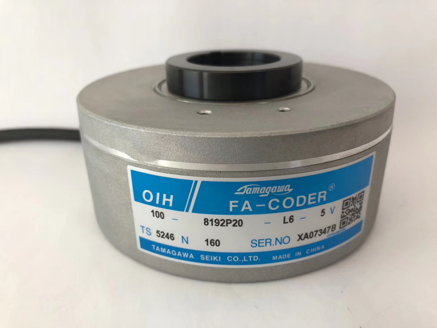
OIH60 |
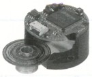
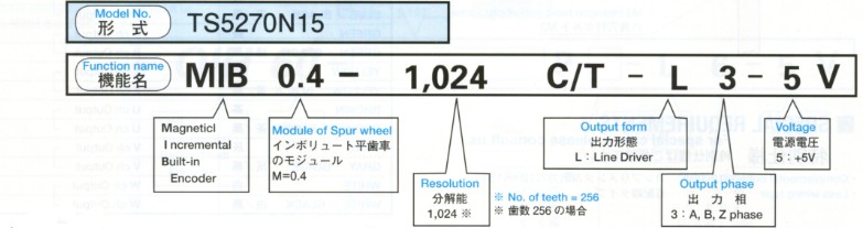
MIB0.4 |
TS517 |
ts54 |
ts52 n3 |
ts52 n5 |
ts52 n4 |
ts5270 |
 |
 |
 |
 |
 |
 |
| 19, 20 | 21, 22 | 23, 24 | 25, 26 | 27, 28 | 29, 30 |
| 9600~50000C/T | 90k~480k C/T | 500~3000C/T | 1000~6000C/T | 1000~8192C/T | 1024C/T (No.of teeth=256) |
| A, B, EU, EV, EW, Phase | A, B, Z Phase | A, B, Z, EU, EV, EW Phase | A, B, Z Phase | ||
| 1.5MHz | 500kHz | 200kHz | 200kHz | ||
| DC+5V | |||||
| 250mA Max | 200mA Max | 300mA Max | |||
| Line Driver | |||||
| 19.6N (2kgf) |
98N (10kgf) |
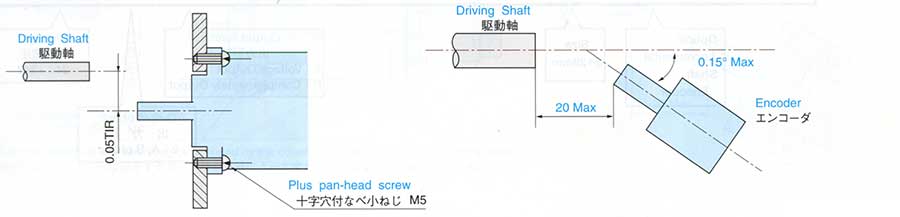
Mounting Tolerance Radial 0.05mm TIR Max Axial 0.2mm Max Shaft Runout 0.1° Max |
Air gap in Spur Wheel 0.15±0.01mm Allowable Tolerance Radial ±0.3mm Axial ±0.5mm |
||
| 9.8N (1kgf) |
49N (5kgf) |
||||
| 2.0x10⁻² N.m (200gf.cm Max) |
9.8x10⁻² N.m (1kgf.cm Max) |
5.9x10⁻³ N.m (60gf.cm Max) |
9.8x10⁻³ N.m (100gf.cm Max) |
2.0x10⁻² N.m (200gf.cm Max) |
|
| IP=50 | IP=40 Electronic Circuits Disclosed |
IP=40 | IP=50 | ||
| -10~+85°C | -10~+75°C | -20~+85°C | -10~+80°C | ||
| 49m/s2 (5G) |
98m/s2 (10G) |
49m/s2 (5G) |
Full Amplitude 1.5mm 0.5Hr (5~500Hz) |
||
| 1960m/s2 (200G) |
980m/s2 (100G) |
490m/s2 (50G) |
980m/s2 (100G) |
294m/s2 (30G) |
|
| 1kg Max | 3kg Max | 0.2 kg | 0.3kg | 0.5kg Max | 0.5kg Max |
SPECIFICATION LISt |
Single-Turn Encoder | |||
| Applications | Machines Tools | Press Machines | ||
| Features | Small & Rugged Model | Rugged Model | Rugged Model and Special divitions |
Ultra rugged model with strobe signal |
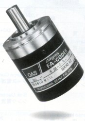
| Series | OAS50 |
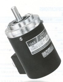
OAS68 |
OAS66 |
OAS66 |
| Model No. | ts5610 |
ts562 |
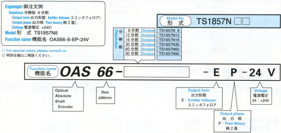
ts1857n |
ts5607n4 |
| External Appearance | 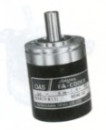 |
 |
 |
 |
| Page | 31, 32 | 33, 34 | 35, 36 | 37, 38 |
| Resolution | 8 bit | 11, 12bit | 8~90 | 0~359C/T |
| Output Phase | Gray | Pure Binary / Gray | Pure Binary | BCD |
| Max Response Frequency | 10kHz | 20kHz | 2.5kHz | |
| Supply Voltage | 120mA Max | 250mA Max | 150mA Max | 300mA Max |
| Output Form | Open Collector | Emitter follower | Open Collector | |
| Shaft Loading (NOTE2) Radial | 98N (10kgf) |
|||
| Shaft Loading (NOTE2) Axial | 49N (5kgf) |
|||
| Starting Torque | 9.8x10⁻³N.m (100gf.cm Max) |
9.8x10⁻²N.m (1kgf.cm Max) |
2.0x10⁻²N.m (200gf.cm Max) |
9.8x10⁻²N.m (1kgf.cm Max) |
| Protection (NOTE3) | IP=50 | IP=52 | IP=53 | IP=50 |
| Operating Temp.Range | -10~+70°C | -10~+60°C | 0~+50°C | |
| Vibration (NOTE4) | 49m/s2 (5G) |
98m/s2 (10G) |
176m/s2 (18G) |
continuous 49m/s2 |
| Shock (NOTE5) | 490m/s2 (50G) |
980m/s2 (100G) |
490m/s2 (50G) |
|
| Mass | 0.5kg Max | 1.5kg Max | 0.6kg Max | |
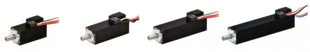
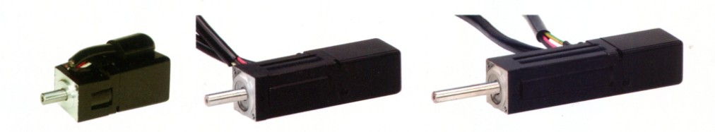
| Multi-Turn Encoder | |||||||
| Motor control, For Robots | Motor control, Machine tools | ||||||
| Small wattage motor, Serial Data transfer |
Middle wattage motor, Serial Data transfer |
Large wattage motor, Serial Data transfer |
|||||
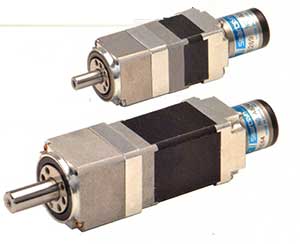
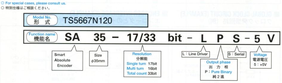
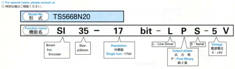
sa35 |
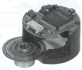
si35 |
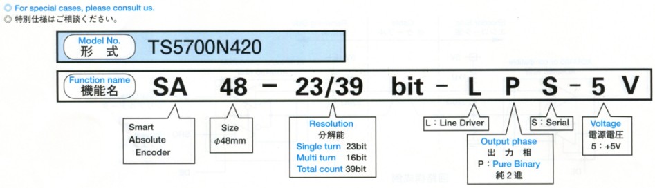
sa48 |
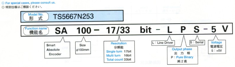
sa100 |
sa135 |
|||
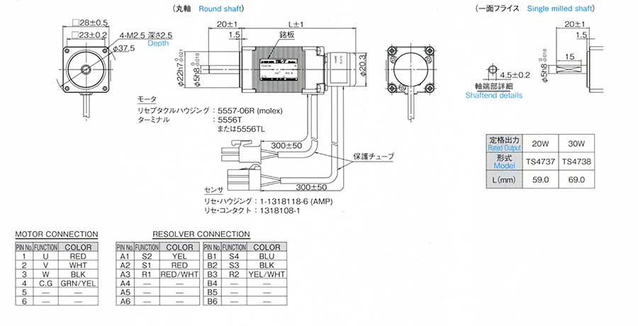
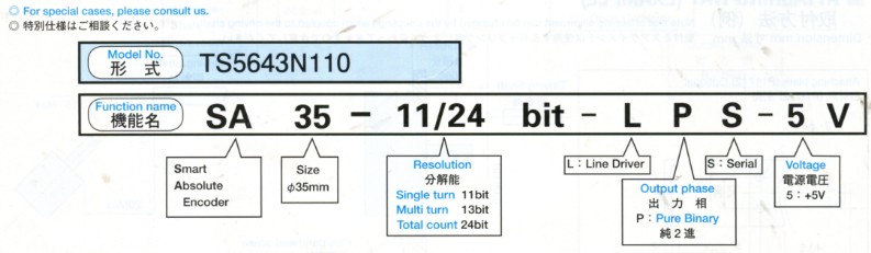
ts5643n110 |
ts5667n120 |
ts5669n220 |
ts5668n20 |
ts5667n420 |
ts5700n420 |
ts5667n253 |
ts5667n650 |
 |
 |
 |
 |
 |
 |
 |
|
| 39, 40 | 43, 44 | 45, 46 | 46, 48 | 49, 50 | 51, 52 | 53, 54 | 55, 56 |
| 11bit/turn and 13bit/Multi-Turns | 17bit/turn and 16bit/Multi-Turns | 17bit/turn | 17bit/turn and 16bit/Multi-Turns | 23bit/turn and 16bit/Multi-Turns | 17bit/turn and 16bit/Multi-Turns | ||
| Pure Binary | |||||||
| Absolute Signal 170kHz Incremental Signal 170kHz |
Absolute Signal 6000min-1 |
Absolute Signal 3000min-1 |
Absolute Signal 1500min-1 |
||||
| DC+5V | |||||||
| 150mA Max Battery operation |
60mA Typ. Battery operation |
110mA Typ. | 110mA Typ | 60mA Typ. Battery operation |
105mA Typ. Battery operation |
70mA Typ. Battery operation |
|
| Line Driver | |||||||
| Mounting Tolerance Radial Axial |
Mounting Tolerance Radial Axial |
||||||
| Shaft Runout | |||||||
| 5.9x10⁻³N.m (60gf.cm Max) |
9.8x10⁻³N.m (100gf.cm Max) |
80x10-3N.m (820gf.cm Max) |
98x10-3N.m (1000gf.cm Max) |
||||
| Not Enclosed | IP40 | ||||||
| -10~+85°C | |||||||
| 98m/s2 (10G) |
49m/s2 (5G) |
||||||
| 1960m/s2 (200G) |
294m/s2 (30G) |
||||||
| 0.3kg Max Without Cable | 0.06kg Max Without Cable | 0.03kg Max Without Cable | 0.08kg Max Without Cable | 1.2kg Max Without Cable | 1.5kg Max Without Cable | ||

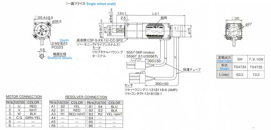
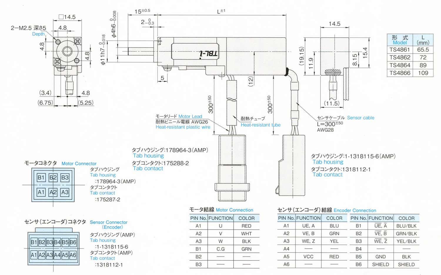
| Electrical Spec. | |
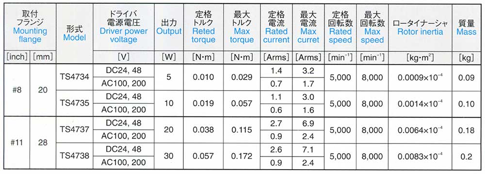
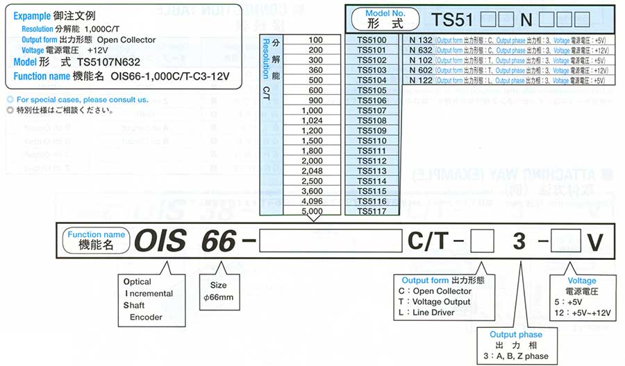
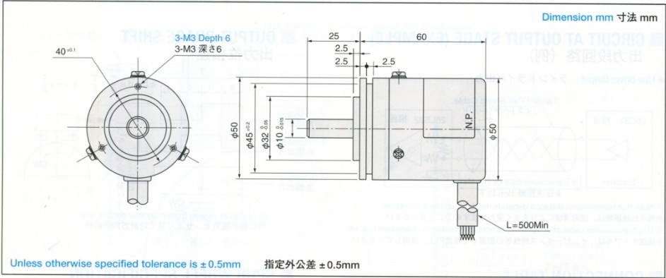
| Resolution | 100~2000 C/T |
| Supply Voltage | DC+5V±5% |
| Consumption Current | 100mA Max |
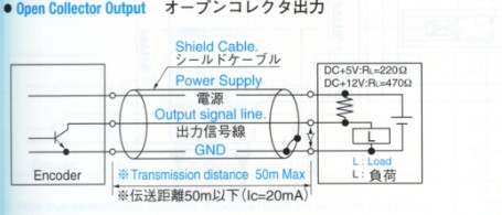
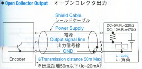
| Output Form Open Collector |
2SC1815 Maximum Allowable Output Voltage 40V Maximum Allowable Sink Current 30mA |
| Maximum Response Frequency | 80kHz |
| Rise time, Fall time | |
| Mechanical Spec. | |
| Starting Torque | 2.9x10⁻³N.m (30gf.cm Max) |
| Moment of Inertia | 2.0x10⁻⁶ kg.m2 (20g.cm2 Max) |
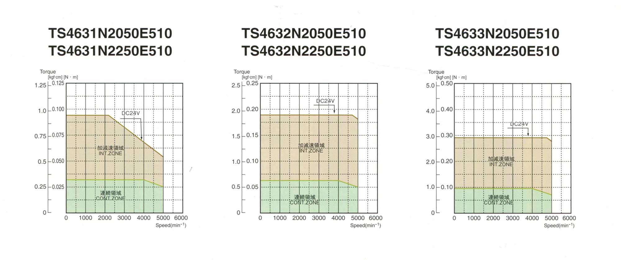
| Maximum Rotating Speed | 5000min-1 (5000rpm) |
| Allowable Shaft Load | Radial 21.6N (2.2kgf Max) |
| Allowable Shaft Load | Axial 12.7N (1.3kgf Max) |
| Operating Temp. Range | 0~+60°C |
| Storage Temp. Range | -20~+85°C |
| Protective Construction | IP=50 |
| Vibration | 49m/s2 (5G) |
| Shock | 490m/s2 (50G) |
| Mass | 0.2kg Max |
| Lead color | Function |
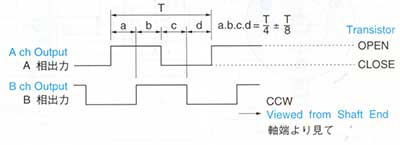
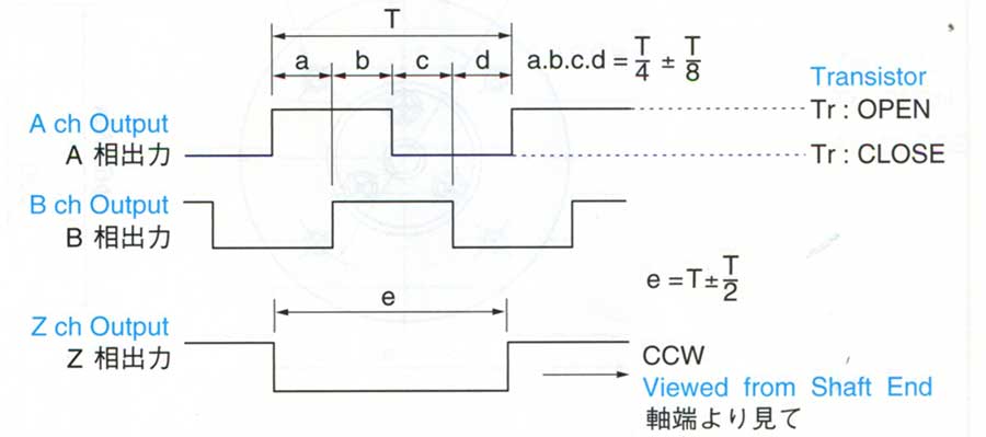
| B L U E | A ch Output |
| G R E E N | B ch Output |
| R E D | DC+5V |
| B L A C K | GND |


| Electrical Spec. | |
| Resolution | 100~2500 C/T |
| Supply Voltage | DC+5V - 5% ~ DC+12V+ 5% DC+5V ±5% |
| Consumption Current | 100mA Max |
| Output Form Open Collector | Maximum Allowable Output Voltage 4V Maximum Allowable Sink Current 30mA |
| Output Form Line Driver | Source Current 20mA Max Sink Current 20mA Max |
| Maximum Response Frequency | 200kHz |
| Rise time, Fall time | (Line Driver) 200nsec |
| Mechanical Spec. | |
| Starting Torque | 4.4x10⁻³N.m (45gf.cm Max) |
| Moment of Inertia | 1.5x10⁻⁶kg.m2 (15g.cm2 Max) |
| Maximum Rotating Speed | 5000min-1 (5000rpm) |
| Allowable Shaft Load Radial | 21.6N (2.2kgf Max) |
| Allowable Shaft Load Axial | 10.8N (1.1kgf Max) |
| Operating Temp. Range | O.C -10~+70°C |
| Operating Temp. Range | L.D 0~+75°C |
| Storage Temp. Range | -20~+85°C |
| Protective Construction | IP=50 |
| Vibration | 49m/s2 (5G) |
| Shock | 490m/s2 (50G) |
| Mass | 0.15kg Max |
| Lead color | Open Collector Output | Line Driver Output |
| R E D | DC+5V ~+12V | DC+5V |
| B L A C K | GND | GND |
| Y E L L O W | Z ch Output | A ch Output |
| W H I T E | GND | A ch Output |
| B L U E | A ch Output | B ch Output |
| G R E E N | B ch Output | B ch Output |
| B R O W N | Z ch Output | |
| O R A N G E | Z ch Output |


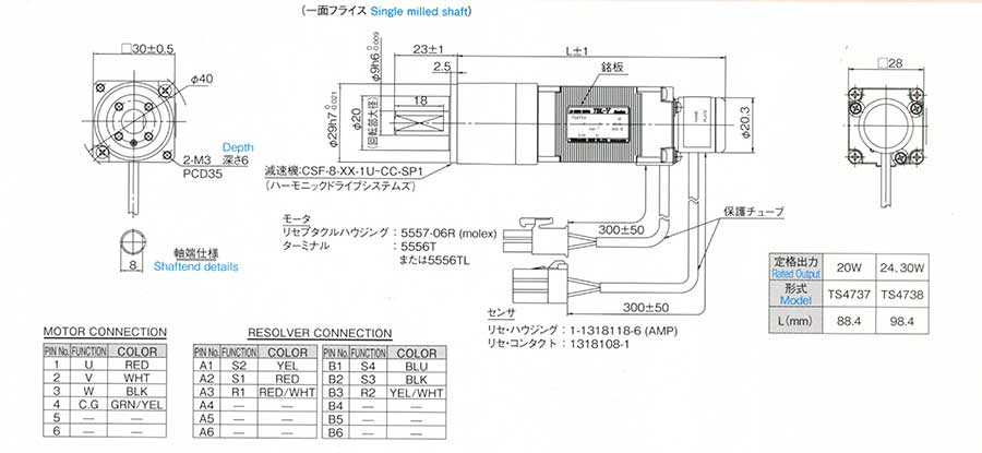
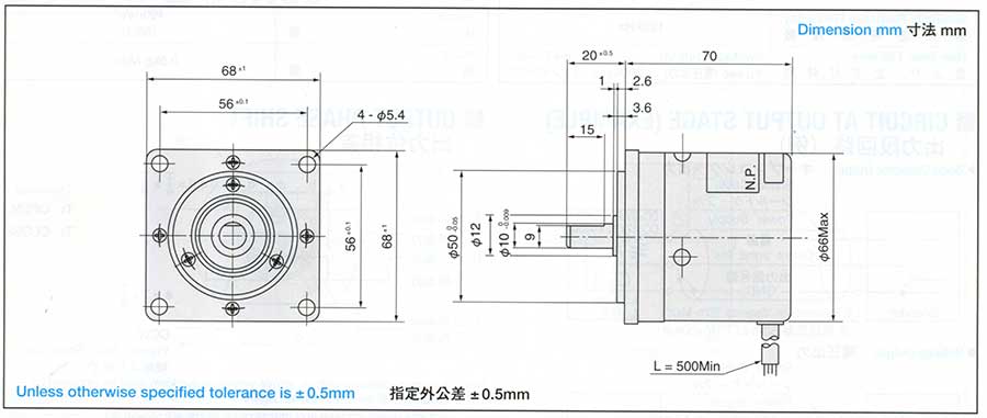
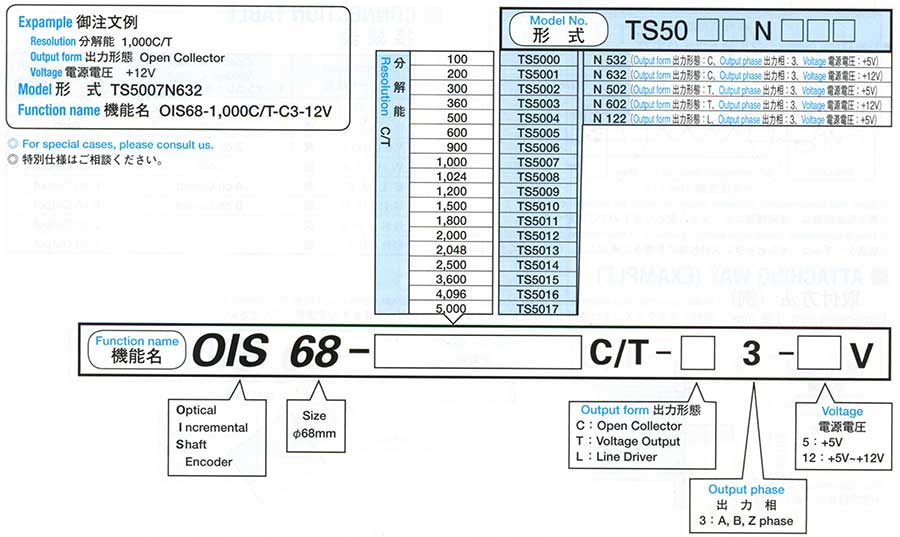
| Electrical Spec. | |||
| Resolution | 100~5000 C/T | ||
| Supply Voltage | DC+5V±5% | DC+12V±5% | |
| Consumption Current | 200mA Max | ||
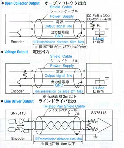
| Output Form | Open Collector | Maximum Allowable Output Voltage 40V Maximum Allowable Sink Current 30mA |
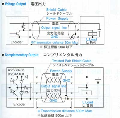
|
| Voltage Output | H = DC+2.4V Min L + DC+0.4V Max |
H = DC+10V Min L = DC+1V Max |
|
| Line Driver | SN75113 Source Current 40mA Max Sink Current 40mA Max |
||
| Maximum Response Frequency | 125kHz | ||
| Rise time, Fall time | (Voltage Output) | (Line Driver) 200nsec |
|
| Mechanical Spec. | |
| Starting Torque | 2.9x10⁻³N.m (30gf.cm Max) |
| Moment of Inertia | 3.0x10⁻⁶kg.m2 (30kg.cm2 Max) |
| Maximum Rotating Speed | 7200min -1 (7200rpm) |
| Allowable Shaft Load | Radial 21.6N (2.2kgf Max) |
| Allowable Shaft Load | Axial 12.7N (1.3kgf Max) |
| Operating Temp. Range | -10~+70°C |
| Storage Temp. Range | -20~+85°C |
| Protective Construction | IP=50 |
| Vibration | 49m/s 2 (5G) |
| Shock | 490m/s 2 (50G) |
| Mass | 0.5kg Max |

| Lead color | Open Collector Voltage Output |
Line driver Output |
| R E D | DC+5V / DC+12V | DC+5V |
| B L A C K | GND | GND |
| Y E L L O W | Z ch Output | A ch Output |
| W H I T E | GND | A ch Output |
| B L U E | A ch Output | B ch Output |
| G R E E N | B ch Output | B ch Output |
| B R O W N | Z ch Output | |
| O R A N G | Z ch Output |
| Electrical Spec. | |||
| Resolution | 100~5000 C/T | ||
| Supply Voltage | DC+5V±5% | DC+12V±5% | |
| Consumption Current | 200mA Max | ||
| Output Form | Open Collector | Maximum Allowable Output Voltage 40v Maximum Allowable Sink Current 30mA |
|
| Voltage Output | H = DC+2.4V Min L = DC+0.4 Max |
H = DC+10V Min L = DC+0.4V Max |
|
| Line Driver | SN75113 Source Current 40mA Max Sink Current 40mA Max |
||
| Maximum Response Frequency | 125kHz | ||
| Rise time, Fall time | (Voltage Output) | (Line driver) 200nsec |
|
| Mechanical Spec. | |
| Starting Torque | 9.8x10 -2 N.m (1kgf.cm Max) |
| Moment of Inertia | 3.0x10 -6kg.m 2 (30g.cm 2 Max) |
| Maximum Rotating Speed | 7200min -1 (7200rpm) |
| Allowable Shaft Load Radial | 98N (10kgf Max) |
| Allowable Shaft Load Axial | 49N (5kgf Max) |
| Operating Temp. Range | ~10+70°C |
| Storage Temp. Range | -20~+85°C |
| Protective Construction | IP=52 |
| Vibration | 98m/s 2 (10G) |
| Shock | 980m/s 2 (100G) |
| Mass | 1kg Max |
| Lead color | Open Collector Voltage Output |
Line Driver Output |
| R E D | DC+5V / DC+12V | DC+5V |
| B L A C K | GND | GND |
| Y E L L O W | Z ch Output | A cha Output |
| W H I T E | GND | A ch Output |
| B L U E | A ch Output | B ch Output |
| G R E E N | B ch Output | B ch Output |
| B R O W N | Z ch Output | |
| O R A N G E | Z ch Output |

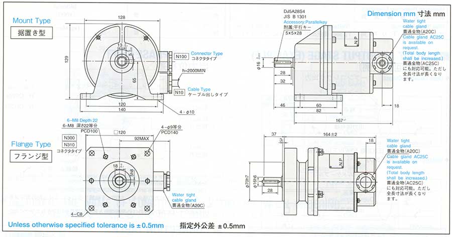
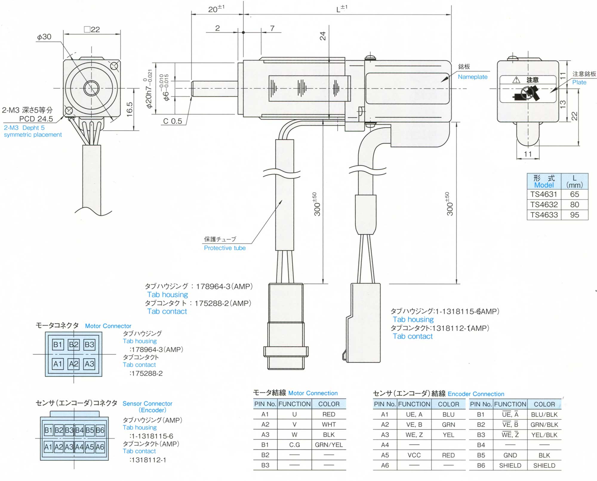
| Electrical Spec. | |
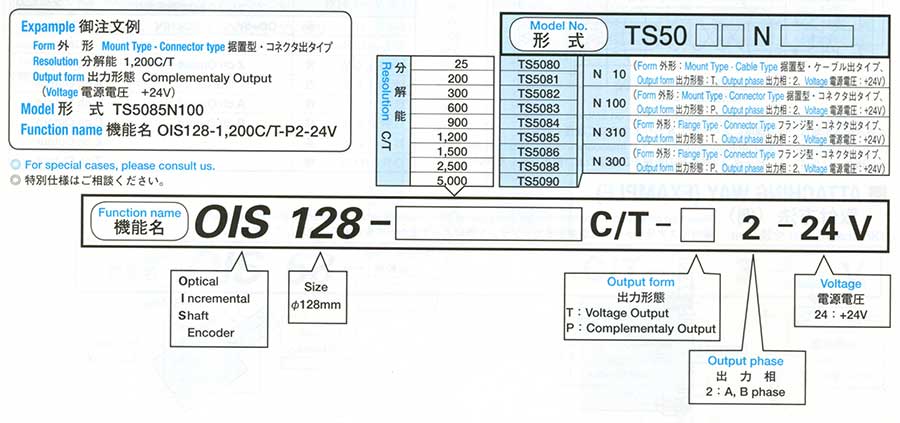
| Resolution | 25C/T~5000C/T |
| Supply Voltage | DC+24V±20% |
| Consumption Current | 300mA Max |
| Output Form Voltage Output | H = DC+24V±20% L = DC+0.5V Max |
| Output Form Complementaly Output | H = DC+24V±20 L = DC+1.1V Max |
| Maximum Response Frequency | 25kHz |
| Rise time, Fall time | 5 sec Max |
| Mechanical Spec. | |
| Starting Torque | 0.2N.m (2kgf.cm Max) |
| Moment of Inertia | 5.0x10 -5 kg.m 2 (500g.cm 2 Max) |
| Maximum Rotating Speed | 2500min -1 (2500rpm) |
| Allowable Shaft Load Radial | 392N (40kgf Max) |
| Allowable Shaft Load Axial | 49N (5kgf Max) |
| Operating Temp. Range | 0~+50°C |
| Storage Temp. Range | -20~+85°C |
| Protective Construction | IP=57 |
| Vibration | 98m/s 2 (10G) |
| Shock | 980m/s 2 (100G) |
| Mass | Mount Type 7kg Max, 8kg Max Flange Type |
| PIN | Function | ||
| N10 | N100, 300, 310 | Voltage Output | Complementaly Output |
| RED | 1 | DC+24V | DC+24V |
| BLACK | 2 | GND | GND |
| WHITE | 3 | GND | Ach Output |
| BROWN | 4 | Ach Output | GND |
| GREEN | 5 | Bch Output | Bch Output |
| 6 | GND | ||

| Electrical Spec. | |
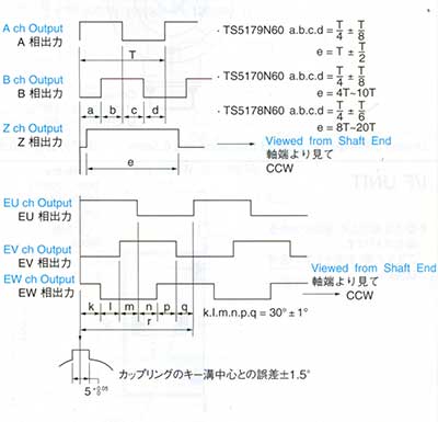
| Resolution | 9600~50000 C/T |
| Supply Voltage | DC+5V±5% |
| Consumption Current | 250mA Max |
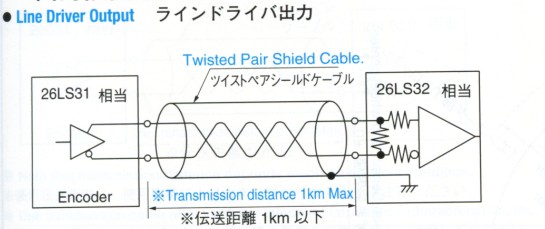
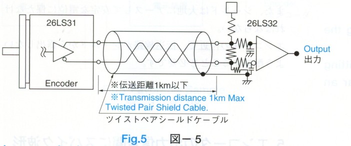
| Output Form Line Driver | 26LS31 Source Current 20mA Max Sink Current 20mA Max |
| Maximum Response Frequency | 9600C/T 576kHz |
| 25000C/T 1.5MHz | |
| 50000C/T 2.5MHz | |
| Rise time, Fall time | 200nsec |
| Mechanical Spec. | |
| Starting Torque | 2.0x10 -2N.m (200gf.cm Max) |
| Moment of Inertia | 2.0x10 -5 kg.m 2 (200g.cm 2 Max) |
| Maximum Rotating Speed | 5000min -1 (5000rpm) |
| Allowable Shaft Load Radial | 19.6N (2kgf Max) |
| Allowable Shaft Load Axial | 9.8N (1kgf Max) |
| Operating Temp. Range | -10~+85°C |
| Storage Temp. Range | -20~+90°C |
| Protective Construction | IP=52 |
| Vibration | 49m/s 2 (5G) |
| Shock | 1960m/s 2 (200G) |
| Mass | 1kg Max |

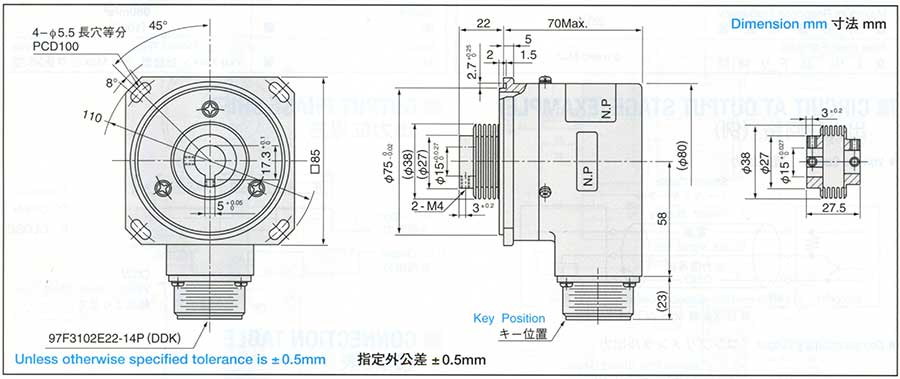
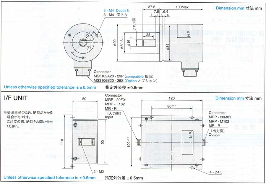
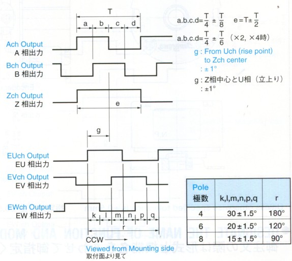
| 97F3102E22-14P | |||
| PIN | Function | PIN | Function |
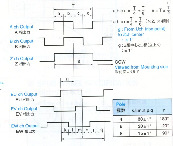
| A | A ch Output | K | V ch Output |
| B | A ch Output | L | V ch Output |
| C | B ch Output | M | W ch Output |
| D | B ch Output | T | W ch Output |
| F | Z ch Output | S | DC+5V |
| G | Z ch Output | R | GND |
| H | U ch Output | ||
| J | U ch Output | N | Case GND |

| Electrical Spec. | |
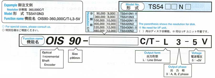
| Resolution | 90000C/T, 100000C/T, 120000C/T, 360000C/T, 400000C/T, 480000C/T |
| Supply Voltage | DC+5V±5% |
| Consumption Current | 500mA Max |
| Output Form Line Driver | 26LS31 Source Current 20mA Max Sink Current 20mA Max |
| Maximum Response Frequency | 500kHz |
| Rise time, Fall time | 200nsec |
| Mechanical Spec. | |
| Starting Torque | 9.8x10 -2N.m (1kgf.cm Max) |
| Moment of Inertia | 3.0x10 -5 kg.m 2 (200g.cm 2 Max) |
| Maximum Rotating Speed | 5000min -1 (5000rpm) |
| Allowable Shaft Load Radial | 98N (10kgf Max) |
| Allowable Shaft Load Axial | 49N (5kgf Max) |
| Operating Temp. Range | -10~+75°C |
| Storage Temp. Range | -20~+85°C |
| Protective Construction | IP=52 |
| Vibration | 98m/s 2 (10G) |
| Shock | 980m/s 2 (100G) |
| Mass | 3kg Max |


| Electrical Spec. | |
| Resolution | 500~600 C/T |
| Supply Voltage | DC+5V±5% |
| Consumption Current | 200mA Max |
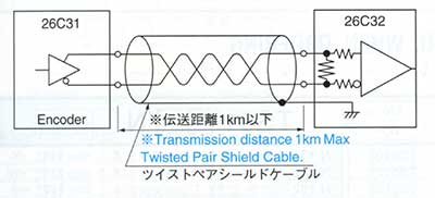
| Output Form Line Driver | 26C31 Source Current 20mA Max Sink Current 20mA Max |
| Maximum Response Frequency | 200kHz |
| Rise time, Fall time | 100nsec, Max |
| Mechanical Spec. | |
| Starting Torque | 5.9x10 -3N.m (60gf.cm Max) |
| Moment of Inertia | 1.0x10 -6 kg.m 2 (10g.cm 2 Max) |
| Maximum Rotating Speed | 6000min -1 (6000rpm) |
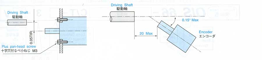
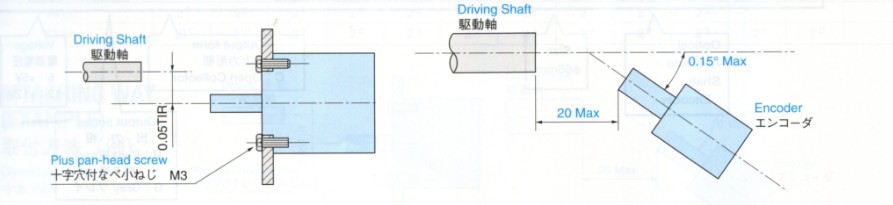
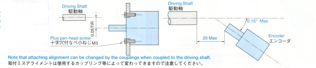
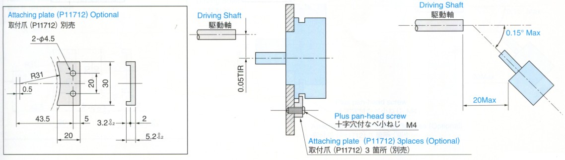
| Mounting Tolerance Radial Play | 0.05mm TIR Max |
| Mounting Tolerance Axial | 0.2mm Max |
| Mounting Tolerance Shaft Inclination | 0.1° Max |
| Operating Temp. Range | -20~+85°C |
| Storage Temp. Range | -25~+85°C |
| Protective Construction | IP=40 Electronic Circuits Disclosed |
| Vibration | 49m/s 2 (5G) |
| Shock | 490m/s 2 (50G) |
| Mass | 0.2kg Max |


| Lead color | Line driver Output |
| RED | DC+5V |
| BLACK | GND |
| BLUE | A ch Output |
| BLUE / BLACK | A ch Output |
| GREEN | B ch Output |
| GREEN / BLACK | B ch Output |
| YELLOW | Z ch Output |
| YELLOW / BLACK | Z ch Output |
| BRWON | U ch Output |
| BROWN / BLACK | U ch Output |
| GRAY | V ch Output |
| GRAY / BLACK | V ch Output |
| WHITE | W ch Output |
| WHITE / BLACK | W ch Output |
| Electrical Spec. | |
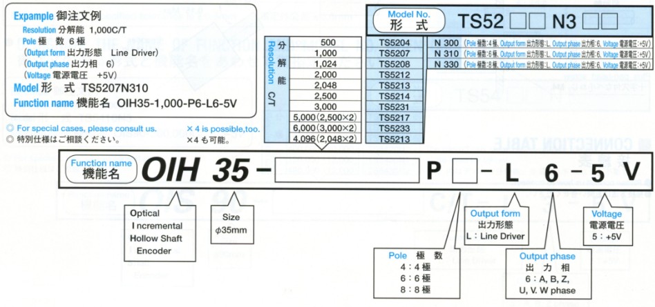
| Resolution | 1000~12000 C/T |
| Supply Voltage | DC+5V±5% |
| Consumption Current | 200mA Max |
| Output Form Line Driver | 26LS31 Source Current 20mA Max Sink Current 20mA Max |
| Maximum Response Frequency | 200kHz |
| Rise time, Fall time | 100nsec Max |
| Mechanical Spec. | |
| Starting Torque | 9.8x10 -3N.m (100gf.cm Max) |
| Moment of Inertia | 6.5x10 -6 kg.m 2 (65g.cm 2 Max) |
| Maximum Rotating Speed | 6000min -1 (6000rpm) |
| Mounting Tolerance Radial Play | 0.05mm TIR Max |
| Mounting Tolerance Axial | 0.2mm Max |
| Mounting Tolerance Shaft Inclination | 0.1° Max |
| Operating Temp. Range | -20~+85°C |
| Storage Temp. Range | -25~+85°C |
| Protective Construction | IP=40 |
| Vibration | 49m/s 2 (5G) |
| Shock | 980m/s 2 (100G) |
| Mass | 0.3kg Max |

| Lead color | Line driver Output |
| RED | DC+5V |
| BLACK | GND |
| BLUE | A ch Output |
| BLUE / BLACK | A ch Output |
| GREEN | B ch Output |
| GREEN / BLACK | B ch Output |
| YELLOW | Z ch Output |
| YELLOW / BLACK | Z ch Output |
| BRWON | U ch Output |
| BROWN / BLACK | U ch Output |
| GRAY | V ch Output |
| GRAY / BLACK | V ch Output |
| WHITE | W ch Output |
| WHITE / BLACK | W ch Output |

| Electrical Spec. | |
| Resolution | 1000~8192 C/T |
| Supply Voltage | DC+5V±5% |
| Consumption Current | 200mA Max |
| Output Form Line Driver | 26LS31 Source Current 20mA Max Sink Current 20mA Max |
| Maximum Response Frequency | 200kHz |
| Rise time, Fall time | 100nsec Max |
| Mechanical Spec. | |
| Starting Torque | 9.8x10 -3N.m (100gf.cm Max) |
| Moment of Inertia | 6.5x10 -6 kg.m 2 (65g.cm 2 Max) |
| Maximum Rotating Speed | 6000min -1 (6000rpm) |
| Mounting Tolerance Radial Play | 0.05mm TIR Max |
| Mounting Tolerance Axial | 0.2mm Max |
| Mounting Tolerance Shaft Inclination | 0.1° Max |
| Operating Temp. Range | -20~+85°C |
| Storage Temp. Range | -25~+85°C |
| Protective Construction | IP=40 |
| Vibration | 49m/s 2 (5G) |
| Shock | 980m/s 2 (100G) |
| Mass | 0.5kg Max |
| Lead color | Line driver Output |
| RED | DC+5V |
| BLACK | GND |
| BLUE | A ch Output |
| BLUE / BLACK | A ch Output |
| GREEN | B ch Output |
| GREEN / BLACK | B ch Output |
| YELLOW | Z ch Output |
| YELLOW / BLACK | Z ch Output |
| BRWON | U ch Output |
| BROWN / BLACK | U ch Output |
| GRAY | V ch Output |
| GRAY / BLACK | V ch Output |
| WHITE | W ch Output |
| WHITE / BLACK | W ch Output |

| Electrical Spec. | |
| Resolution | 1024 C/T No. of teeth = 256 |
| Supply Voltage | DC+5V+5% / DC+5V-10% |
| Consumption Current | 300mA Max |
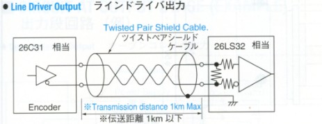
| Output Form Line Driver | 26C31 Source Current 20mA Max Sink Current 20mA Max |
| Maximum Response Frequency | 200kHz |
| Rise time, Fall time | |
| Mechanical Spec. | |
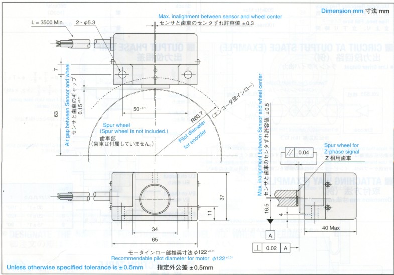
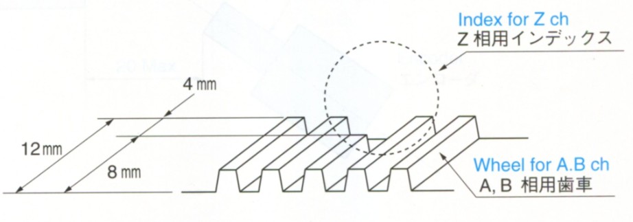
| Air gap between Sensor or wheel | 0.15±0.01mm |
| Radial Inalignment btwn Sensor or wheel | ±0.3mm |
| Axial Inalignment btwn Sensor or wheel | ±0.5mm |
| Operating Temp. Range | -10~+80°C |
| Storage Temp. Range | -20~+100°C |
| Protective Construction | IP=50 |
| Vibration | Full Amplitude 1.5mm 0.5Hr (5~500Hz) |
| Shock | 294m/s 2 (30G) 11m sec 3 axes 6directions. 10 times each |
| Mass | 0.5kg Max |
| Lead color | Function |
| RED | DC+5V |
| BLACK | GND |
| BLUE | A ch Output |
| BLUE / BLACK | A ch Output |
| GREEN | B ch Output |
| GREEN / BLACK | B ch Output |
| YELLOW | Z ch Output |
| YELLOW / BLACK | Z ch Output |
| Sheild | Case GND |
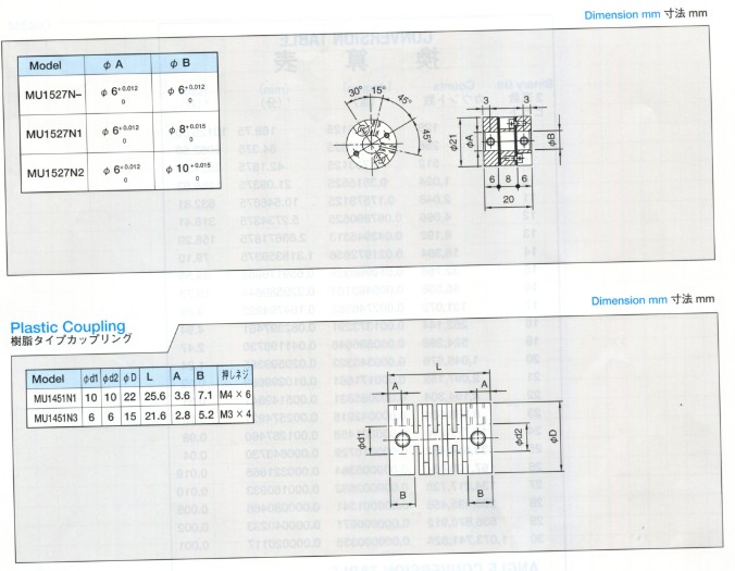
| Model No. | No. of type | Outer Dia. | Inner Dia. |
| MU1528N45 | 256 | Ø 103.2±0.02 | Ø 45 +0.0110 |
| MU1528N50 | 256 | Ø 103.2±0.02 | Ø 50 +0.0110 |

| No. of teeth | 256 |
| Module | 0.4 |
| Pressure Angle | 20° |
| Accuracy | JGMA3~4 |
| Tooth Thickness | 8mm |
| Outer Dia.runout against Inner dia. | 0.2 TIR Max |
| No. of teeth | 1 |
| Module | 0.4 |
| Pressure Angle | 20° |
| Accuracy | JGMA3~4 |
| Tooth Thickness | 4mm |

| Electrical Spec. | |
| Resolution | 8bit |
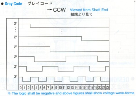
| Output Phase | Gray Code |
| Supply Voltage | DC+5V±5% |
| Consumption Current | 120mA Max |
| Output Form Open Driver | TD62503F Maximum Allowable Output Voltage 24V Maximum Allowable Sink Current 80mA |
| Maximum Response Frequency | 10kHz |
| Rise time, Fall time | |
| Mechanical Spec. | |
| Starting Torque | 9.8x10 -2N.m (1kgf.cm Max) |
| Moment of Inertia | 3.0x10 -6 kg.m 2 (30g.cm 2 Max) |
| Maximum Rotating Speed | 3000min -1 (3000rpm) |
| Allowable Shaft Load Radial | 98N (10kgf Max) |
| Allowable Shaft Load Axial | 49N (5kgf Max) |
| Operating Temp. Range | -10~+70°C |
| Storage Temp. Range | -20~+85°C |
| Protective Construction | IP=50 |
| Vibration | 49m/s 2 (5G) |
| Shock | 490m/s 2 (50G) |
| Mass | 0.5kg Max |
| Lead color | Function | Lead color | Function | Lead color | Function |
| B R O W N | 1ST Digit (MSB) 2 7 | G R E E N | 5TH Digit 2 3 | B L A C K | GND |
| R E D | 2ND Digit 2 6 | B L U E | 6th Digit 2 2 | W H I T E | DC+5V |
| O R A N G E | 3RD Digit 2 5 | V I O L E T | 7TH Digit 2 1 | ||
| Y E L L O W | 4TH Digit 2 4 | G R A Y | 8TH Digit(LSB) 2 0 |
| Electrical Spec. | |
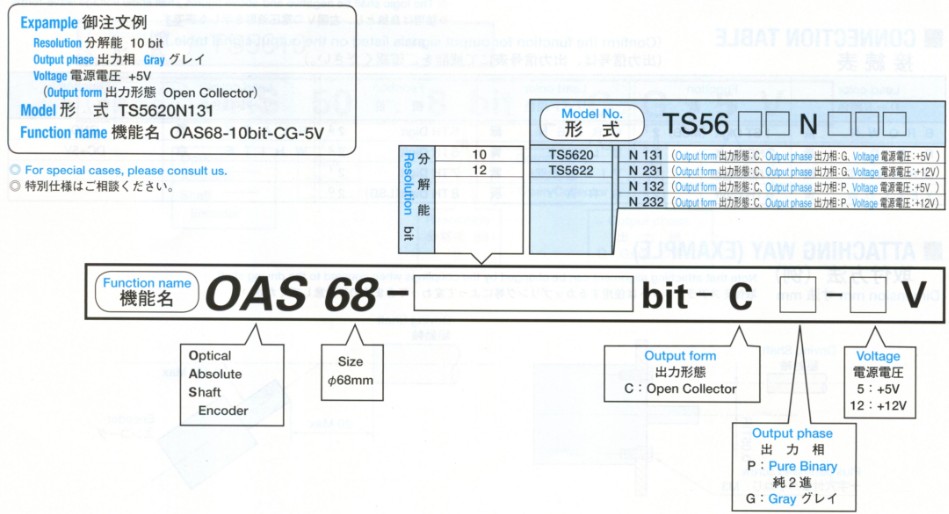
| Resolution | 10bit, 12bit |
| Output Phase | Pure Binary Code, Gray Code |
| Supply Voltage | DC+5V±5% / DC+12V±5% |
| Consumption Current | 250mA Max |
| Output Form Open Driver | TD62503F Maximum Allowable Output Voltage 24V Maximum Allowable Sink Current 80mA |
| Maximum Response Frequency | 10kHz |
| Rise time, Fall time | |
| Mechanical Spec. | |
| Starting Torque | 9.8x10 -2N.m (1kgf.cm Max) |
| Moment of Inertia | 3.0x10 -6 kg.m 2 (30g.cm 2 Max) |
| Maximum Rotating Speed | 5000min -1 (5000rpm) |
| Allowable Shaft Load Radial | 98N (10kgf Max) |
| Allowable Shaft Load Axial | 49N (5kgf Max) |
| Operating Temp. Range | -10~+70°C |
| Storage Temp. Range | -20~+85°C |
| Protective Construction | IP=52 |
| Vibration | 98m/s 2 (10G) |
| Shock | 980m/s 2 (100G) |
| Mass | 1.5kg Max |

| Pin | Function | Pin | Function | Pin | Function |
| 1 | 1ST Digit (MSB) | 9 | 9TH Digit (LSB) | 17 | |
| 2 | 2ND Digit | 10 | 10TH Digit (LSB) | 18 | DC+5V |
| 3 | 3RD Digit | 11 | 11TH Digit (LSB) | 19 | |
| 4 | 4TH Digit | 12 | 12TH Digit (LSB) | 20 | |
| 5 | 5TH Digit | 13 | 21 | ||
| 6 | 6TH Digit | 14 | 22 | Case GND | |
| 7 | 7TH Digit | 15 | GND | 23 | |
| 8 | 8TH Digit | 16 | GND | 24 Note | Reverse Count |
| Resolution \ Digit | 1ST | 2ND | 3RD | 4TH | 5TH | 6TH | 7TH | 8TH | 9TH | 10TH | 11TH | 12TH | 13TH |
| 10bit | 2 9 | 2 8 | 2 7 | 2 6 | 2 5 | 2 4 | 2 3 | 2 2 | 2 1 | 2 0 | |||
| 12bit | 2 11 | s 10 | 2 9 | 2 8 | 2 7 | 2 6 | 2 5 | 2 4 | 2 3 | 2 2 | 2 1 | 2 0 |

| Electrical Spec. | |
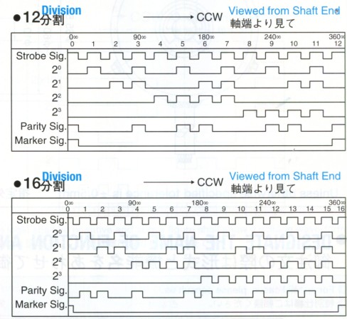
| Resolution | 8~90 Division |
| Output Phase | Pure Binary Code |
| Supply Voltage | DC+24V±5% |
| Consumption Current | 150mA Max |
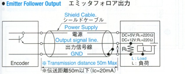
| Output Form Emitter follower | Maximum Allowable Output Voltage 50V Maximum Allowable Sink Current 200mA |
| Maximum Response Frequency | 20kHz |
| Rise time, Fall time | |
| Mechanical Spec. | |
| Starting Torque | 2.0x10 -2N.m (200gf.cm Max) |
| Moment of Inertia | 3.0x10 -6 kg.m 2 (30g.cm 2 Max) |
| Maximum Rotating Speed | 5000min -1 (5000rpm) |
| Allowable Shaft Load Radial | 98N (10kgf Max) |
| Allowable Shaft Load Axial | 49N (5kgf Max) |
| Operating Temp. Range | -10~+60°C |
| Storage Temp. Range | -20~+85°C |
| Protective Construction | IP=53 |
| Vibration | 176m/s 2 (18G) |
| Shock | 980m/s 2 (100G) |
| Mass | 0.6kg Max |
| Lead color | Function | Lead color | Function |
| V I O L E T | DC+24V | RED | 2 0 |
| WHITE | GND | ORANGE | 2 1 |
| GRAY | GND | YELLOW | 2 2 |
| BLACK | Parity Sig. | GREEN | 2 3 |
| BROWN | Storobe Sig. |


| Electrical Spec. | |
| Resolution | 0~359C/T |
| Output Phase | BCD Code |
| Supply Voltage | DC+12V±10% |
| Consumption Current | 300mA Max |
| Output Form Open follower | Maximum Allowable Output Voltage 28V Maximum Allowable Sink Current 50mA |
| Maximum Response Frequency | 2.5kHz |
| Rise time, Fall time | 1.5 sec Max |
| Mechanical Spec. | |
| Starting Torque | 9.8x10 -2N.m (1kgf.cm Max) |
| Moment of Inertia | 3.0x10 -6 kg.m 2 (30g.cm 2 Max) |
| Maximum Rotating Speed | 5000min -1 (5000rpm) |
| Allowable Shaft Load Radial | 98N (10kgf Max) |
| Allowable Shaft Load Axial | 49N (5kgf Max) |
| Operating Temp. Range | 0~+50°C |
| Storage Temp. Range | -20~+85°C |
| Protective Construction | IP=50 |
| Vibration | 49m/s 2 (18G), 98m/s 2 (10G) ~ 500Hz |
| Shock | 490m/s 2 (50G), 11m sec. |
| Mass | Without Cable 0.6kg Max |

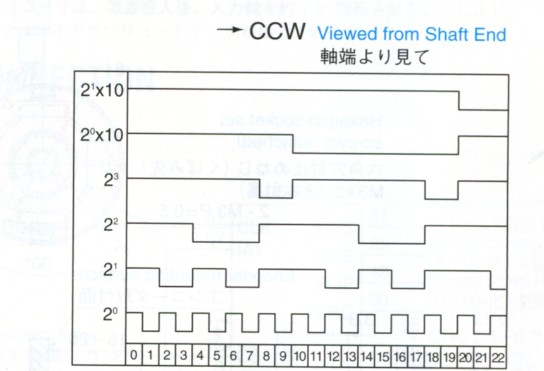
| Lead color | Function | Lead color | Function | Lead color | Function |
| BROWN | B2 (x200) (MSB) | BLUE | A1 (x10) | WHITE/VIOLET | DC+12V |
| RED | A2 (x100) | VIOLET | D0 (x8) | WHITE/GRAY | GND |
| ORANGE | D1 (x80) | GRAY | C0 (x4) | WHITE/GRAY | GND |
| YELLOW | C1 (x40) | WHITE | B0 (x2) | BLACK | Reverse Count |
| GREEN | B1 (x20) | WHITE/BLACK | A0 (x1) (LSB) | WHITE/BROWN | Busy Signal |
| Electrical Spec. | |
| Resolution Absolute Signal | 11bit/turn and 13bit/8,192 turns (total 24bit) |
| Resolution Incremental Signal | 2048C/T, 2-Phase output 1C/T, Zch. |
| Output Phase | Pure Binary Code |
| Supply Voltage | DC+5V±5% |
| Consumption Current | 150mA Max Battery operation: 100μA Max |
| Output Form Line follower | 26C31Source Current 20mA Max Sink Current 20mA |
| Maximum Response Frequency | Absolute Signal 170kHz Incremental Signal 170kHz |
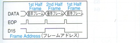
| Serial Data transfer cycle | 84μs |
| Rise time, Fall time | 1.5 sec Max |
| Mechanical Spec. | |
| Starting Torque | 5.9x10 -3N.m (60gf.cm Max) |
| Moment of Inertia | 1.0x10 -6 kg.m 2 (10g.cm 2 Typ) |
| Maximum Rotating Speed | 5000min -1 (5000rpm) |
| Mounting Tolerance Radial Play | 0.05 mm TIR Max |
| Mounting Tolerance Axial End Play | 0.02 mm Max |
| Mounting Tolerance Shaft Inclination | 0.1° Max |
| Operating Temp. Range | -10~+85°C |
| Storage Temp. Range | -20~+90°C |
| Protective Construction | Not Enclosed |
| Vibration | 98m/s 2 (10G) (5-2000Hz) for 2 hours |
| Shock | 1960m/s 2 (200G), 11msec, 3times |
| Mass | Without Cable 0.3kg Max |
| Supply Voltage | 5.0±10% |
| Consumption Current | ±40mA Max |
| Permissible Voltage | Max: VDD Min: VSS |
| Output Current/terminal | ±24mA Max |
| Permissible Dissipation | 100mW Max |
| Operating Temperature | -20~+85°C |
| Storage Temperature | -55~+150°C |

| Electrical Spec. | |
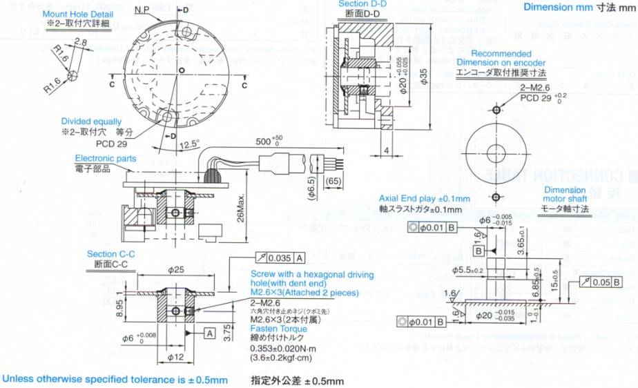
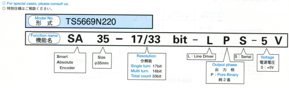
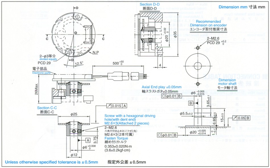
| Resolution Absolute Signal | 17bit/turn and 16bit multiturns (total 33bit) |
| Output Phase | Pure Binary Code |
| Supply Voltage | DC+5V±5% |
| Consumption Current | (Typ) Normal Operation 60mA (Typ) Battery Operation 100μA |
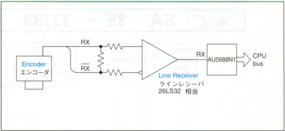
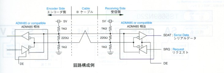
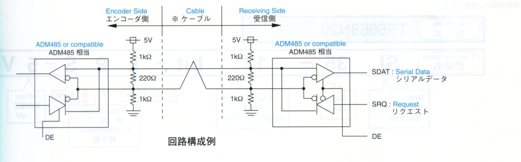
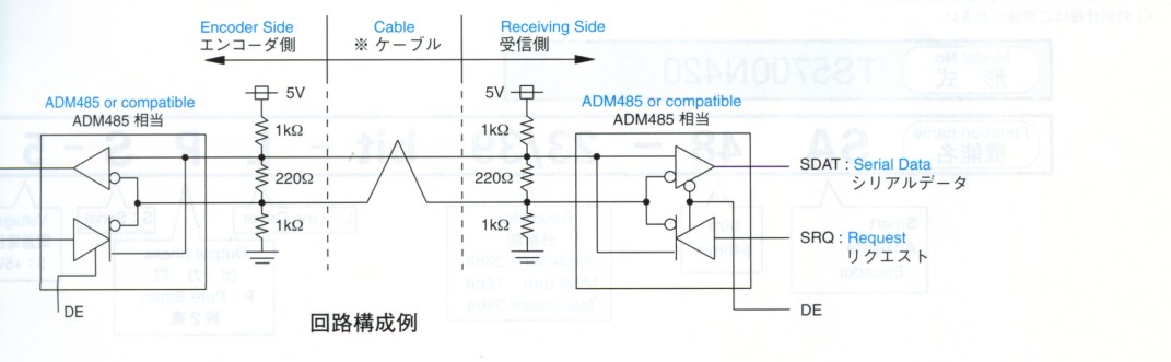
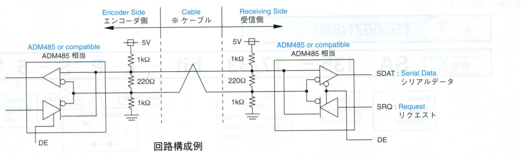
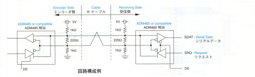
| Output Form Line Driver | ADM485 or compatible/20mA |
| Maximum Response Frequency | 6000min -1 Max (6000rpm) |
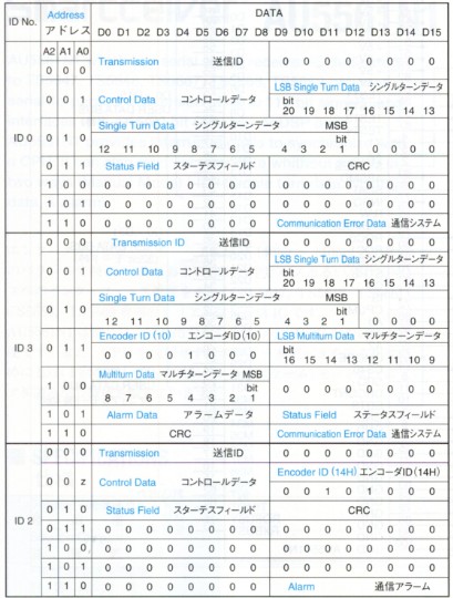
| Serial Data transfer cycle | 35μs~63μs (Note) Including time for a request. Time depends on the ID Codes. 2.5Mbit/sec Start-Stop transmission. |
| Rise time, Fall time | Base Band NRZ (Bi-direction) |
| Mechanical Spec. | |
| Starting Torque | 5.9x10 -3N.m (60gf.cm Max) |
| Moment of Inertia | 1.0x10 -6 kg.m 2Typ |
| Maximum Rotating Speed | 6000min -1 (6000rpm) Max |
| Mounting Tolerance Radial Play | 0.05 mm TIR Max |
| Mounting Tolerance Axial End Play | 0.01 mm Max |
| Mounting Tolerance Shaft Inclination | 0.1° Max |
| Operating Temp. Range | -10~+85°C |
| Storage Temp. Range | -20~+90°C |
| Protective Construction | Not Enclosed |
| Vibration | 98m/s 2 (10G) (5-2000Hz) for 2 hours |
| Shock | 1960m/s 2 (200G), 11msec, 3times |
| Mass | Without Cable 0.06kg Max |
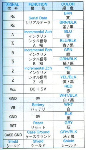
| Lead Wire | Function | Remark |
| Red | Vcc | Main Power DC+5V±5% |
| Black | GND | |
| Brown | VB | Battery (Note1) |
| Brown/Black | GND | |
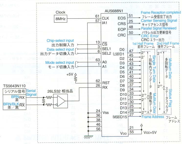
| Blue | SD | Serial Data |
| Blue/Black | SD | |
| Gray | CASE GND |

| Electrical Spec. | |
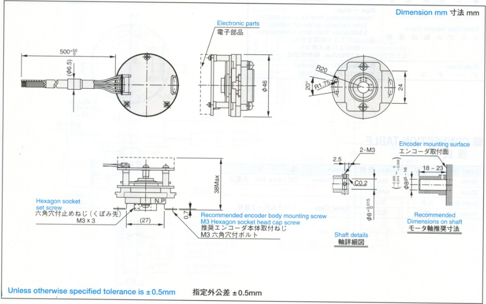
| Resolution Absolute Signal | 17bit/turn and 16bit multiturns (total 33bit) |
| Output Phase | Pure Binary Code |
| Supply Voltage | DC+5V+10% / DC+5V-5% |
| Consumption Current | (Typ) Normal Operation 100mA (Typ) Battery Operation 100μA/3.6V |
| Output Form Line Driver | ADM485 or compatible/20mA |
| Maximum Response Frequency | 6000min -1 Max (6000rpm) |
| Serial Data transfer cycle | 35μs~63μs (Note) Including time for a request. Time depends on the ID Codes. 2.5Mbit/sec Start-Stop transmission. |
| Rise time, Fall time | Base Band NRZ (Bi-direction) |
| Mechanical Spec. | |
| Moment of Inertia | 0.24x10 -6 kg.m 2Typ |
| Maximum Rotating Speed | 6000min -1 (6000rpm) Max |
| Operating Temp. Range | -10~+85°C |
| Storage Temp. Range | -20~+90°C |
| Protective Construction | Not Enclosed |
| Vibration | 98m/s 2 (10G) (5-2000Hz) for 2 hours |
| Shock | 1960m/s 2 (200G), 11msec, 3times |
| Mass | Without Cable 0.06kg Max |
| Lead Wire | Function | Remark |
| Red | Vcc | Main Power DC+5V±5% |
| Black | GND | |
| Brown | VB | Battery (Note1) |
| Brown/Black | GND | |
| Blue | SD | Serial Data |
| Blue/Black | SD | |
| Gray | CASE GND |
| Electrical Spec. | |
| Resolution Absolute Signal | 17bit/turn |
| Output Phase | Pure Binary Code |
| Supply Voltage | DC+5V±5% |
| Consumption Current | (Typ) Normal Operation 100mA |
| Output Form Line Driver | ADM485 or compatible/20mA |
| Maximum Response Frequency | 6000min -1 Max (6000rpm) |
| Serial Data transfer cycle | 35μs~63μs (Note) Including time for a request. Time depends on the ID Codes. 2.5Mbit/sec Start-Stop transmission. |
| Rise time, Fall time | Base Band NRZ (Bi-direction) |
| Mechanical Spec. | |
| Moment of Inertia | 0.24x10 -6 kg.m 2Typ |
| Maximum Rotating Speed | 6000min -1 (6000rpm) Max |
| Operating Temp. Range | -10~+85°C |
| Storage Temp. Range | -20~+90°C |
| Protective Construction | Not Enclosed |
| Vibration | 98m/s 2 (10G) (5-2000Hz) for 2 hours |
| Shock | 1960m/s 2 (200G), 11msec, 3times |
| Mass | Without Cable 0.03kg Max |
| Lead Wire | Function | Remark |
| White | Vcc | Main Power DC+5V±5% |
| Black | GND | |
| Light Blue | SD | Serial Data |
| Purple | SD |


| Electrical Spec. | |
| Resolution Absolute Signal | 17bit/turn and 16bit multiturns (total 33bit) |
| Output Phase | Pure Binary Code |
| Supply Voltage | DC+5V±5% |
| Consumption Current | (Typ) Normal Operation 60mA (Typ) Battery Operation 100μA/3.6V |
| Output Form Line Driver | ADM485 or compatible/20mA |
| Maximum Response Frequency | 6000min -1 Max (6000rpm) |
| Serial Data transfer cycle | 35μs~63μs (Note) Including time for a request. Time depends on the ID Codes. 2.5Mbit/sec Start-Stop transmission. |
| Rise time, Fall time | Base Band NRZ (Bi-direction) |
| Mechanical Spec. | |
| Starting Torque | 9.8x10 -3N.m (100gf.cm) Max |
| Moment of Inertia | 6.5x10 -6 kg.m 2Typ |
| Maximum Rotating Speed | 6000min -1 (6000rpm) Max |
| Mounting Tolerance Radial Play | 0.05 mm TIR Max |
| Mounting Tolerance Axial End Play | 0.01 mm Max |
| Mounting Tolerance Shaft Inclination | 0.1° Max |
| Operating Temp. Range | -10~+85°C |
| Storage Temp. Range | -20~+90°C |
| Protective Construction | Not Enclosed |
| Vibration | 98m/s 2 (10G) (5-2000Hz) for 2 hours |
| Shock | 1960m/s 2 (200G), 11msec, 3times |
| Mass | Without Cable 0.08kg Max |
| Lead Wire | Function | Remark |
| Red | Vcc | Main Power DC+5V±5% |
| Black | GND | |
| Brown | VB | Battery (Note 1) |
| Brown/Black | GND | |
| Blue | SD | Serial Data |
| Blue/Black | SD | |
| Gray | CASE GND |
| Electrical Spec. | |
| Resolution Absolute Signal | 23bit/turn and 16bit multiturns (total 39bit) |
| Output Phase | Pure Binary Code |
| Supply Voltage | DC+5V±5% |
| Consumption Current | (Typ) Normal Operation 105mA (Typ) Battery Operation 100μA/3.6V |
| Output Form Line Driver | ADM485 or compatible/20mA |
| Maximum Response Frequency | 6000min -1 Max (6000rpm) |
| Serial Data transfer cycle | 35μs~63μs (Note) Including time for a request. Time depends on the ID Codes. 2.5Mbit/sec Start-Stop transmission. |
| Rise time, Fall time | Base Band NRZ (Bi-direction) |
| Mechanical Spec. | |
| Starting Torque | 9.8x10 -3N.m (100gf.cm) Max |
| Moment of Inertia | 6.5x10 -6 kg.m 2Typ |
| Maximum Rotating Speed | 6000min -1 (6000rpm) Max |
| Mounting Tolerance Radial Play | 0.05 mm TIR Max |
| Mounting Tolerance Axial End Play | 0.01 mm Max |
| Mounting Tolerance Shaft Inclination | 0.1° Max |
| Operating Temp. Range | -10~+85°C |
| Storage Temp. Range | -20~+90°C |
| Protective Construction | Not Enclosed |
| Vibration | 98m/s 2 (10G) (5-2000Hz) for 2 hours |
| Shock | 1960m/s 2 (200G), 11msec, 3times |
| Mass | Without Cable 0.08kg Max |
| Lead Wire | Function | Remark |
| Red | Vcc | Main Power DC+5V±5% |
| Black | GND | |
| Brown | VB | Battery (Note 1) |
| Brown/Black | GND | |
| Blue | SD | Serial Data |
| Blue/Black | SD | |
| Gray | CASE GND |


| Electrical Spec. | |
| Resolution Absolute Signal | 17bit/turn and 16bit multiturns (total 33bit) |
| Output Phase | Pure Binary Code |
| Supply Voltage | DC+5V±5% |
| Consumption Current | (Typ) Normal Operation 70mA (Typ) Battery Operation 100μA/3.6V |
| Output Form Line Driver | ADM485 or compatible/20mA |
| Maximum Response Frequency | 6000min -1 Max (6000rpm) |
| Serial Data transfer cycle | 35μs~63μs (Note) Including time for a request. Time depends on the ID Codes. 2.5Mbit/sec Start-Stop transmission. |
| Rise time, Fall time | Base Band NRZ (Bi-direction) |
| Mechanical Spec. | |
| Starting Torque | 80x10 -3N.m (820gf.cm) Max |
| Moment of Inertia | 150x10 -6 kg.m 2Typ |
| Maximum Rotating Speed | 3000min -1 (3000rpm) Max |
| Mounting Tolerance Radial Play | 0.05 mm TIR Max |
| Mounting Tolerance Axial End Play | 0.01 mm Max |
| Mounting Tolerance Shaft Inclination | 0.1° Max |
| Operating Temp. Range | -10~+85°C |
| Storage Temp. Range | -20~+90°C |
| Protective Construction | IP=40 |
| Vibration | 49m/s 2 (5G) (5-2000Hz) for 2 hours |
| Shock | 1960m/s 2 (200G), 11msec, 3times |
| Mass | Without Cable 1.2kg Max |
| Lead Wire | Function | Remark |
| Red | Vcc | Main Power DC+5V±5% |
| Black | GND | |
| Brown | VB | Battery (Note 1) |
| Brown/Black | GND | |
| Blue | SD | Serial Data |
| Blue/Black | SD | |
| Gray | CASE GND |

| Electrical Spec. | |
| Resolution Absolute Signal | 17bit/turn and 16bit multiturns (total 33bit) |
| Output Phase | Pure Binary Code |
| Supply Voltage | DC+5V±5% |
| Consumption Current | (Typ) Normal Operation 70mA (Typ) Battery Operation 100μA/3.6V |
| Output Form Line Driver | ADM485 or compatible/20mA |
| Maximum Response Frequency | 1500min -1 Max (1500rpm) |
| Serial Data transfer cycle | 35μs~63μs (Note) Including time for a request. Time depends on the ID Codes. 2.5Mbit/sec Start-Stop transmission. |
| Rise time, Fall time | Base Band NRZ (Bi-direction) |
| Mechanical Spec. | |
| Starting Torque | 98x10 -3N.m (1000gf.cm) Max |
| Moment of Inertia | 1.21x10 -3 kg.m 2Typ |
| Maximum Rotating Speed | 1500min -1 (1500rpm) Max |
| Mounting Tolerance Radial Play | 0.05 mm TIR Max |
| Mounting Tolerance Axial End Play | 0.1 mm Max |
| Mounting Tolerance Shaft Inclination | 0.1° Max |
| Operating Temp. Range | -10~+85°C |
| Storage Temp. Range | -20~+90°C |
| Protective Construction | IP=40 |
| Vibration | 49m/s 2 (5G) (5-2000Hz) for 2 hours |
| Shock | 1960m/s 2 (200G), 11msec, 3times |
| Mass | Without Cable 1.5kg Max |
| Lead Wire | Function | Remark |
| Red | Vcc | Main Power DC+5V±5% |
| Black | GND | |
| Brown | VB | Battery (Note 1) |
| Brown/Black | GND | |
| Blue | SD | Serial Data |
| Blue/Black | SD | |
| Gray | CASE GND |
| Supply Voltage | 5.0V±10% |
| Source Current | 40mA Max |
| Permissible Voltage | Max: VDD Min: VSS |
| Output Current/Terminal | ±24mA Max |
| Permissible Dissipation | ±200mW Max |
| Operating Temperature | -20~+85°C |
| Storage Temperature | -65~+150°C |
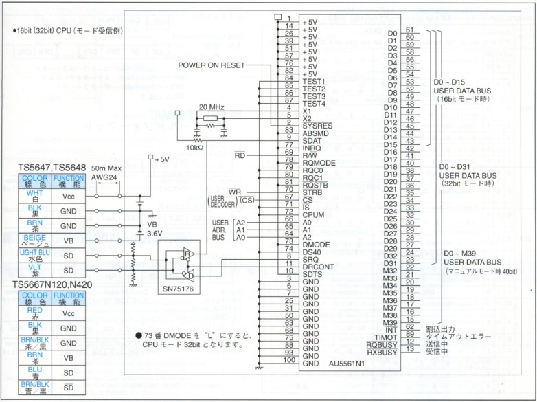
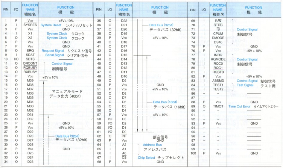

| Designation | I/O/T | Description of Function | PIN No. |
| SRQ | O | Request Data output | 8 |
| SDTS | IPU/O/T | Input/output terminal for both for Serial Data and Request Data. Usually receiving mode except during transmission of ID code. Fixed to "H" when it is not used | 10 |
| DRCONT | O | It is used for controlling bi-directional line driver. Output is usually "L", and "H" during only transmitting. Open state when it is not used. | 11 |
| D0~D15 | I/O/T | Usually 16-bits input/output data bus line. Request Data is written here. Exclusive use for output in manual mode. | See connection table |
| D16~D31 | O/T | Upper side of data bus line. Tri-state for 32 bits mode. No connection for 16 bits mode. Exclusive use for output in manual mode. | See connection table |
| M32~M39 | O | Upper side of data bus line. Use only in manual mode and exclusive use for output. | See connection table |
| dmode | ipu | Data Mode Control input. Input of "L" for 32-bit mode and input of "H" for 16-bit mode. | 73 |
| test1~test4 | ipd | Test terminal for simulation. Usually fixed to "L". | 84~87 |
| rqbusy | o | Request Busy signal. "L" is during transmitting Monitor signal shown that ASIC is during transmitting. | 12 |
| rxbusy | 0 | Receiving Busy signal "L" is during receiving. Monitor signal shown that ASIC is during receiving. | 13 |
| ds40 | ipu | Selecting data in manual mode. | 74 |
| timot | o | Time-out Error. "H" output when serial data is not returned for Transmitting Request according to para. 10.3.6. | 89 |
| sysres | ipu | System Reset input. AU5561 N1 is reset and return to initial condition for "L". Request can not be transmitted within 6μs after reset is released. | 2 |
| absmd | i | Receiving format select. "H" for 21, 20, 17 and 16 bits encoder, "L" for 14 and 13 bits. | 83 |
| Designation | I/O/T | Description of Function | PIN No. |
| x1 | i | 20MHz Clock input. 20MHz ±0.05% | 4 |
| x2 | o | 20MHz Clock output. Reverse phase X1 | 5 |
| sdat | i | Serial Data input | 9 |
| inrq | i | Selecting input in manual mode for request tigger source of RQSTB (external) or 1 00ps (internally generated.). | 77 |
| int | o | Interrupt output signal. "L" is set when data is completed to receive. It is reset when output data is once read out by RD. DSP mode is reset by IS and CS. Store signal (L) of 1 ps is transmitted in manual mode. | 62 |
| cpum | ipu | Selecting input of DSP or CPU (common 86, etc.) mode. "L"for CPU mode "H" for DSP mode. | 72 |
| cs | ipu | Control signal for ASIC. "L" for operating and "H"for non-operating I/O of ASIC. Transmitting/receiving block of ASIC operates Independently of CS. It is used for input of address code. | 67 |
| rq mode | i | Request is changed to manual mode for "L" only when DMODE is 16 bits mode. | 78 |
| rq rtb | i | Peculiar Request code is transmitted for applying "L" in manual mode request. | 81 |
| rqc0 rqc1 |
i | Request code is decided in manual mode according. | 79 80 |
| is | ipu | Used with CS in DSP mode for synchronizing of DSP. "L" is set for CPU mode. | 71 |
| R/ | ipu | READ and WRITE signal in DSP mode. Usually set "H" as readout mode. READ signal in CPU mode. | 69 |
| strb | ipu | Indication for the duration of Read or Write. It is used as WRITE signal in CPU mode. | 70 |
| a0 a1 a2 |
i | Address Input terminals. These are used as internal control by connecting with LSB side address from CPU | 66 65 64 |
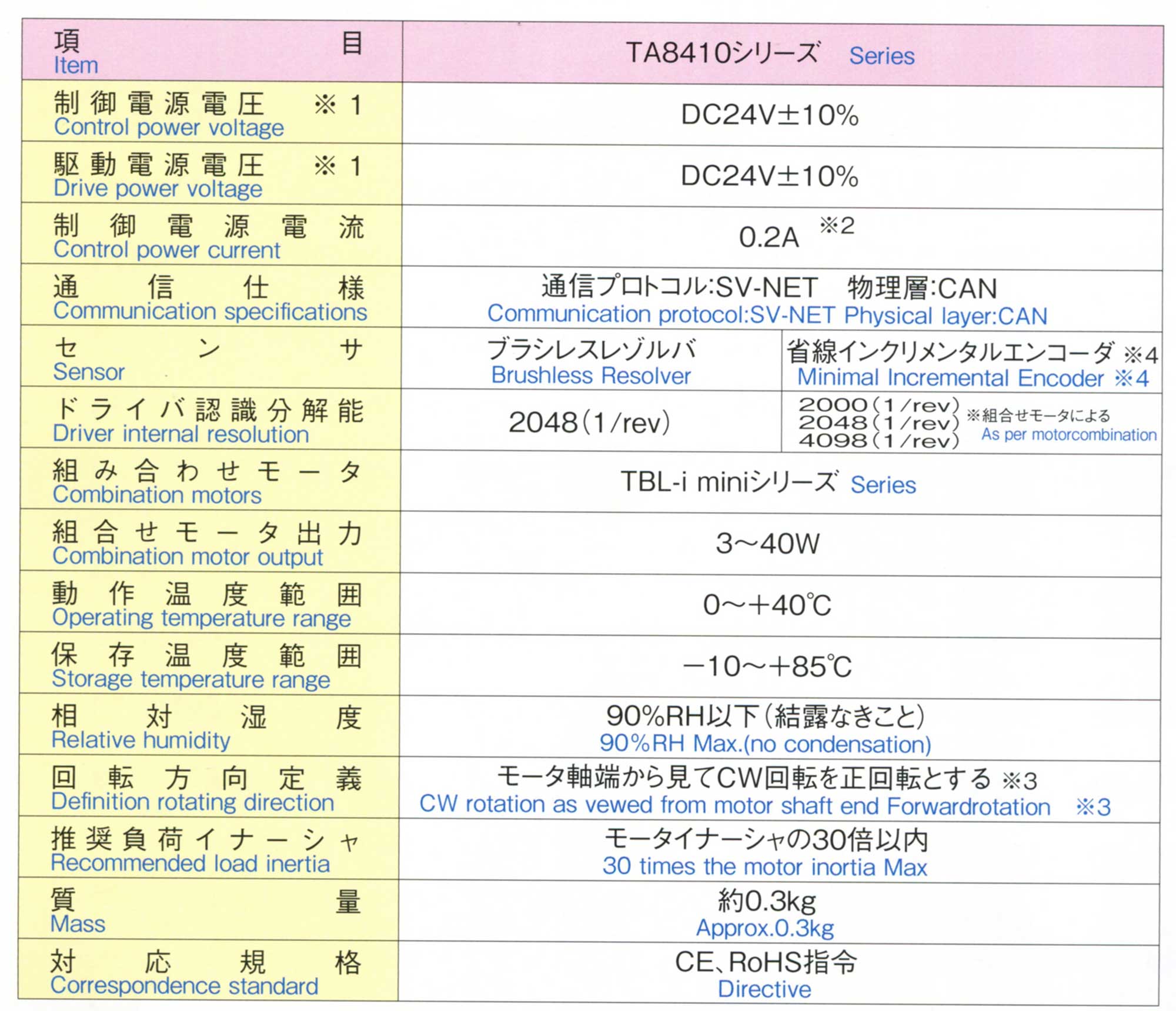
| Item | Specifications | |
| Power Supply | DC24V±10% 0.2A Max | |
| Detector | Sensor Model | Smart Abs TS5667N420 or equivalent |
| Number of axis | 1 axis | |
| Absolute detectable stroke | turns 4096 |
|
| Accuracy | (static condition)[combined sensor] ±0.022° |
|
| Maximum Rotating Speed | 6000min -1(rpm) | |
| Resolution | Sensor 1turn 131072 (17bit) |
|
| Position output | Detectable stroke | (Data increased CCW rotation) PB29bit(CCW) |
| Resolution / turn | 17bit | |
| Multi-Turns Countout | (12 bit Max. in this unit whereas the encoder output is 16 bit Max.) 12bit (16bit Max) | |
| Data renewal cycle | 60μs TYP | |
| Signal output | Transistor open-conllector output BIN DC24V 5~50mA |
|
| Operating Temperature & humidity | Max (Non condensing) 0~+50°C 90%RH |
|
| Mass | (whithout connector) 0.5kg |
|
| Used battery | Lithium battery (TOSHIBA) or equivalent ER17500V/3.6 |
|

| First Coding | Protection Degree |
| 3 (Semi totally-enclosed type) | Ends of solids 2.5mm or over in diameter do not enter inside. |
| 4 (Totally-enclosed type) | Ends of solids 1.0mm or over in diameter do not enter inside. |
| 5 (Dustproof type) | Dust that impairs the designed operation or safety of the rotary encoder do not enter inside. |
| 6 (Dusttight type) | Dust particles do not enter inside. |
| Second Coding | Protection Degree |
| 0 (Open type) | Not protected against entry of water. |
| 2 (Drip-proof 2 type) | Subject to no harmful effects by waterdrops falling at angles 15° or less from vertical. |
| 4 (Spray-proof type) | Subject to no harmful effects by water spray from any direction |
| 3 (Rain-proof type) | Subject to no harmful effects by waterdrops falling at angles 60° or less from vertical. |
| 5 (Jet-proof type) | Subject to no harmful effects by water jets from any direction |
| 6 (Water-proof type) | Impervious to water in strong jets from any direction. (Note 1) |
| 7 (Immersion-proof type) | No water entering when immersed under water at specified pressure for specified time. |


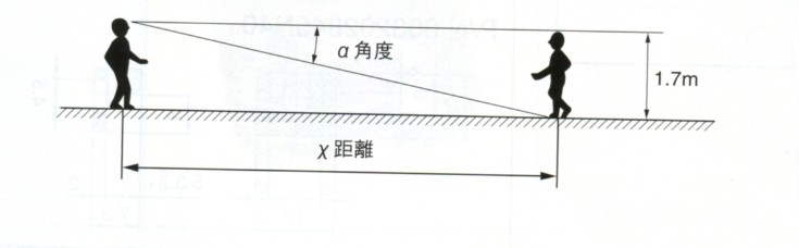
| α | χ 1.7m |
| 10000 | 35m |
| 1000 | 350m |
| 100 | 3.5km |
| 10 | 35km |
| 2 | 180km |
| 1 | 350km |
| 0.6 | 550km |
| 0.5 | 650km |
| 0.1 | 3500km |
| 0.01 | 35000km |


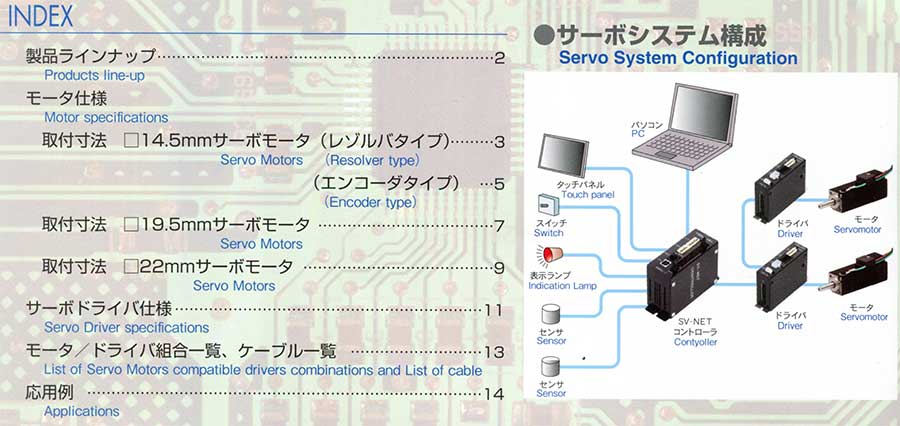


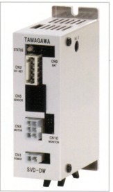
| Main Function | |
| Control commands | Position command input SV-NET or pulse command Speed command input SV-NET or analog command Current command input SV-NET or nalog command |
| Parameter setting functions | Control mode,Position loop gain, Speed loop gain,Speed integration gain, Feed forward, Resonance control filter, Analog command scale setting. Electronic gear setting,Smoothing, Accelerration limit,etc. |
| Protective functions | Sensor error,Drive power error,Over—heat, Over-speed,Overload. Excessive deviation,etc |
| Input and output signals | Servo ON input,A|arm reset input, Alarm output,ln-the-position output, A/B/Z output etc. |